
dsPIC33EP32GS505T-I/PT (TQFP-48-EP(7x7)) — Symbol, Footprint IPC-7351B & 3D STEP Model

dsPIC33EP32GS505T-I/PT

MICROCHIPTQFP-48-EP(7x7) · 48 Pins · Pitch 0.50mmIPC-7351B Verified5.0 (0)
SYNCHRONIZED 4D CROSS-PROBE MODETouch or hover any pin to highlight concurrently across Symbol, Footprint and 3D
1. SYMBOL
U1 · dsPIC33EP32GS505T-I/PT (TQFP-48-EP(7x7))1TMS/ASDA1/RP2RP54/RC63RP55/RC74RP56/RC85RP57/RC96VSS7VCAP8N/C9RP42/PWM3H/R10RP43/PWM3L/R11RPI44/PWM2H/12RPI45/PWM2L/13TDO/RA1014TDI/RA715RPI46/PWM1H/16RPI47/PWM1L/17AVSS18AVDD19MCLR#20N/C21AN0/OA2OUT/R22AN1/C2IN1+/R23IO1224IO1348IO4847RP39/INT0/RB46PGEC2/ASCL2/45PGED2/ASDA2/44N/C43VDD42VSS41SCL1/RPI53/R40SDA1/RPI52/R39SCK1/RPI51/R38SDI1/RPI25/R37IO3736FLT32/SCL2/R35SDA2/RPI24/R34OSC2/CLKO/RA33OSC1/CLKI/RA32N/C31VSS30VDD29IO2928AN7/C3IN1-/C27IO4726IO2125IO14Grid Pitch = 2.54mm (IEEE-315)-20.3-15.2-10.2-5.105.110.215.220.335.630.525.420.315.210.25.10-5.1-10.2-15.2-20.3-25.4-30.5-35.6mm
2. 2D FOOTPRINT
123456789101112131415161718192021222324252627282930313233343536373839404142434445464748E=7.00mm · Pitch e=0.50mmD=7.00mm-7-5-3-113577531-1-3-5-7mm
3. 3D CAD MODEL
Package Body: 7.00mm × 7.00mm · Pitch: 0.50mm · Ruler Step: 1.00mmSynced <100ms

Synchronized Pinout (Symbol / 2D / 3D) (48/48)

Touch or hover any pin to highlight concurrently across Symbol, Footprint and 3D
PinSymbolTypeFunction (EN)
1TMS/ASDA1/RP41/RB9(4)I/OMultiplexed I/O & Peripheral Pin TMS/ASDA1/RP41/RB9(4) (General)
2RP54/RC6I/OMultiplexed I/O & Peripheral Pin RP54/RC6 (General)
3RP55/RC7I/OMultiplexed I/O & Peripheral Pin RP55/RC7 (General)
4RP56/RC8I/OMultiplexed I/O & Peripheral Pin RP56/RC8 (General)
5RP57/RC9I/OMultiplexed I/O & Peripheral Pin RP57/RC9 (General)
6VSSGNDGround Reference Pin (VSS)
7VCAPI/OMultiplexed I/O & Peripheral Pin VCAP (General)
8N/CI/OMultiplexed I/O & Peripheral Pin N/C (General)
9RP42/PWM3H/RB10I/OMultiplexed I/O & Peripheral Pin RP42/PWM3H/RB10 (PWM)
10RP43/PWM3L/RB11I/OMultiplexed I/O & Peripheral Pin RP43/PWM3L/RB11 (PWM)
11RPI44/PWM2H/RB12I/OMultiplexed I/O & Peripheral Pin RPI44/PWM2H/RB12 (PWM)
12RPI45/PWM2L/CTPLS/RB13I/OMultiplexed I/O & Peripheral Pin RPI45/PWM2L/CTPLS/RB13 (PWM)
13TDO/RA10I/OMultiplexed I/O & Peripheral Pin TDO/RA10 (General)
14TDI/RA7I/OMultiplexed I/O & Peripheral Pin TDI/RA7 (General)
15RPI46/PWM1H/T3CK/RB14I/OMultiplexed I/O & Peripheral Pin RPI46/PWM1H/T3CK/RB14 (PWM)
16RPI47/PWM1L/T5CK/RB15I/OMultiplexed I/O & Peripheral Pin RPI47/PWM1L/T5CK/RB15 (PWM)
17AVSSGNDGround Reference Pin (AVSS)
18AVDDPowerPower Supply Input (AVDD — 3.0V to 3.6V)
19MCLR#I/OMultiplexed I/O & Peripheral Pin MCLR# (General)
20N/CI/OMultiplexed I/O & Peripheral Pin N/C (General)
21AN0/OA2OUT/RA0I/OMultiplexed I/O & Peripheral Pin AN0/OA2OUT/RA0 (General)
22AN1/C2IN1+/RA1I/OMultiplexed I/O & Peripheral Pin AN1/C2IN1+/RA1 (General)
23IO12I/OGPIO12 / RTC_GPIO12 / TOUCH12 / ADC2_CH1 / FSPICLK
24IO13I/OGPIO13 / RTC_GPIO13 / TOUCH13 / ADC2_CH2 / FSPIQ
25IO14I/OGPIO14 / RTC_GPIO14 / TOUCH14 / ADC2_CH3 / FSPIWP
26IO21I/OGPIO21 / RTC_GPIO21
27IO47I/OGPIO47 / SPICLK_P_DIFF / SUBSPICLK_P_DIFF
28AN7/C3IN1-/C4IN1-/RC1I/OMultiplexed I/O & Peripheral Pin AN7/C3IN1-/C4IN1-/RC1 (General)
29IO29I/OGeneral Purpose Digital I/O Pin IO29
30VDDPowerPower Supply Input (VDD — 3.0V to 3.6V)
31VSSGNDGround Reference Pin (VSS)
32N/CI/OMultiplexed I/O & Peripheral Pin N/C (General)
33OSC1/CLKI/RA2I/OMultiplexed I/O & Peripheral Pin OSC1/CLKI/RA2 (RTC/CLK)
34OSC2/CLKO/RA3I/OMultiplexed I/O & Peripheral Pin OSC2/CLKO/RA3 (RTC/CLK)
35SDA2/RPI24/RA8I/OMultiplexed I/O & Peripheral Pin SDA2/RPI24/RA8 (I2C)
36FLT32/SCL2/RP36/RB4I/OMultiplexed I/O & Peripheral Pin FLT32/SCL2/RP36/RB4 (I2C)
37IO37I/OGeneral Purpose Digital I/O Pin IO37
38SDI1/RPI25/RA9I/OMultiplexed I/O & Peripheral Pin SDI1/RPI25/RA9 (General)
39SCK1/RPI51/RC3I/OMultiplexed I/O & Peripheral Pin SCK1/RPI51/RC3 (SPI)
40SDA1/RPI52/RC4I/OMultiplexed I/O & Peripheral Pin SDA1/RPI52/RC4 (I2C)
41SCL1/RPI53/RC5I/OMultiplexed I/O & Peripheral Pin SCL1/RPI53/RC5 (I2C)
42VSSGNDGround Reference Pin (VSS)
43VDDPowerPower Supply Input (VDD — 3.0V to 3.6V)
44N/CI/OMultiplexed I/O & Peripheral Pin N/C (General)
45PGED2/ASDA2/RP37/RB5I/OMultiplexed I/O & Peripheral Pin PGED2/ASDA2/RP37/RB5 (General)
46PGEC2/ASCL2/RP38/RB6I/OMultiplexed I/O & Peripheral Pin PGEC2/ASCL2/RP38/RB6 (General)
47RP39/INT0/RB7I/OMultiplexed I/O & Peripheral Pin RP39/INT0/RB7 (General)
48IO48I/OGeneral Purpose Digital I/O Pin IO48
PIN 1 TMS/ASDA1/RP41/RB9(4)
I/O
Multiplexed I/O & Peripheral Pin TMS/ASDA1/RP41/RB9(4) (General)
Design note: Signal terminal TMS/ASDA1/RP41/RB9(4) (I/O, 3.0V to 3.6V domain). Multiplexed alternate functions: TMS/ASDA1/RP41/RB9(4). Supported peripheral buses: General.
IPC-7351B Solder Density & Span C/G/Z Tuner

Extracted Drawings Gallery (6 Standard Drawings + 14 Extracted Figures)

Read the original datasheet PDF directly or click any drawing to view fullscreen
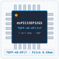
1. Realistic 3D PackageREPRESENTATIVE
dsPIC33EP32GS505T-I/PT (TQFP-48-EP(7x7)) - 1. Realistic 3D Package
Detailed solid 3D bodyExpand ›
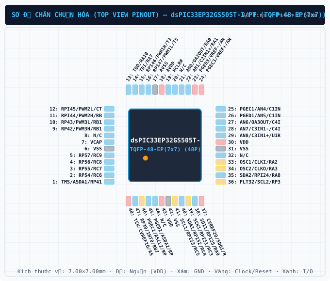
2. Standard Pinout (Top View)CLEANROOM PINOUT
dsPIC33EP32GS505T-I/PT (TQFP-48-EP(7x7)) - 2. Standard Pinout (Top View)
True package pinout (48 pins)Expand ›
3. Original Datasheet PinoutPDF PINOUT
dsPIC33EP32GS505T-I/PT (TQFP-48-EP(7x7)) - 3. Original Datasheet Pinout
Uncropped datasheet pin diagramExpand ›
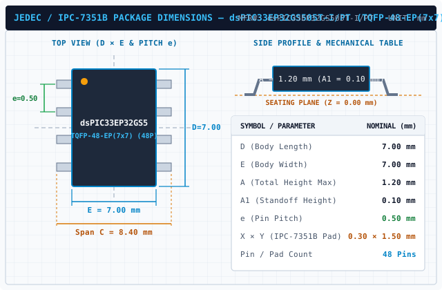
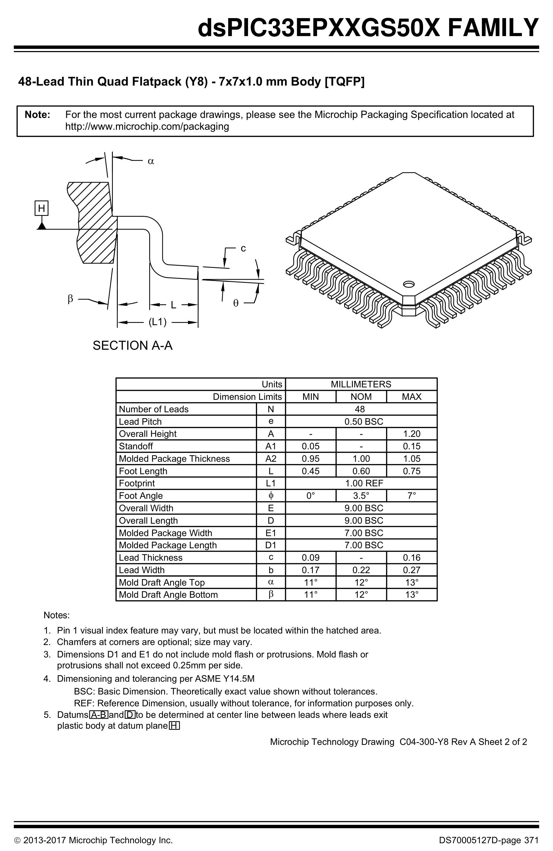
4. Package Dimensions (D×E×A)PACKAGE DIMENSIONS
dsPIC33EP32GS505T-I/PT (TQFP-48-EP(7x7)) - 4. Package Dimensions (D×E×A)
TQFP-48-EP(7x7) · 7.00×7.00mm · Pitch 0.50mmExpand ›
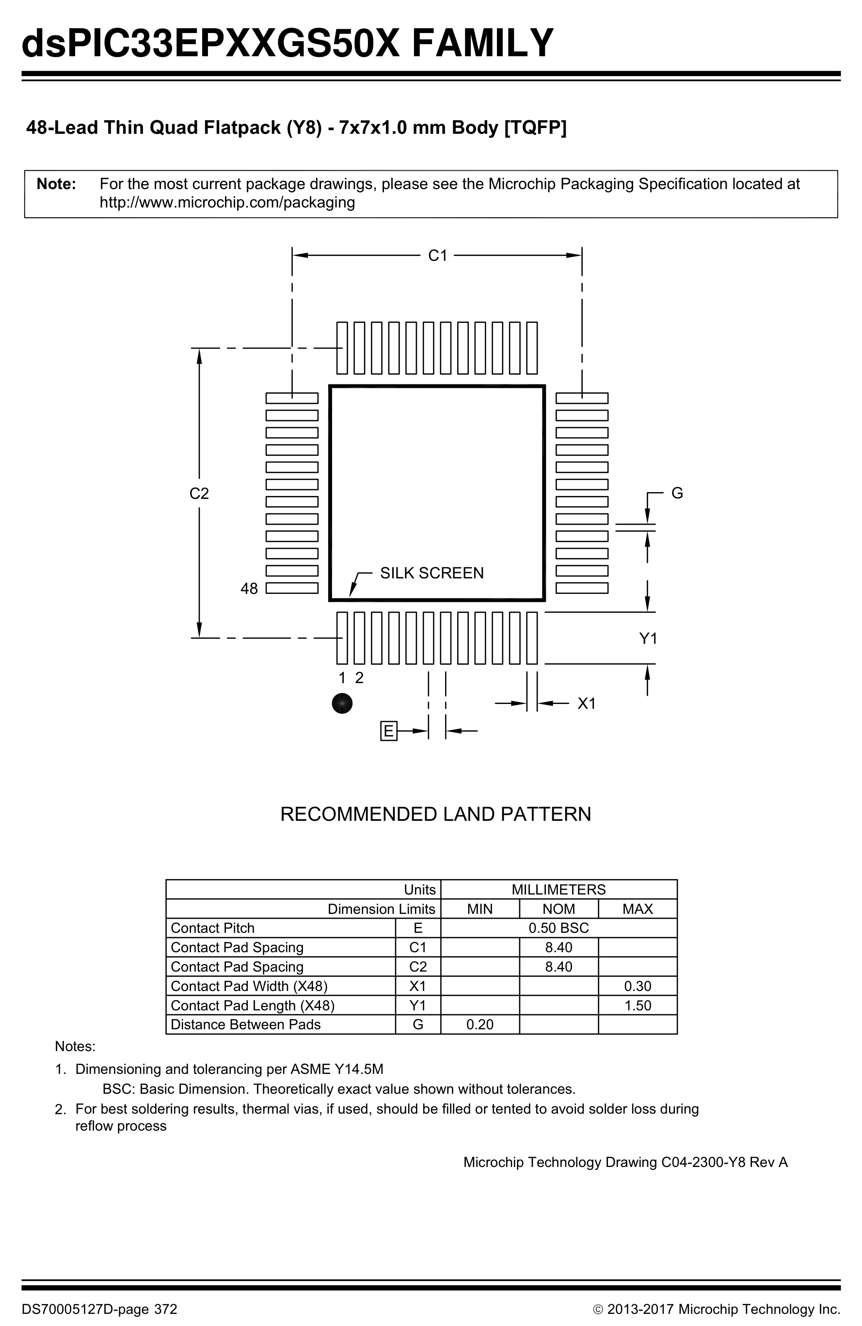
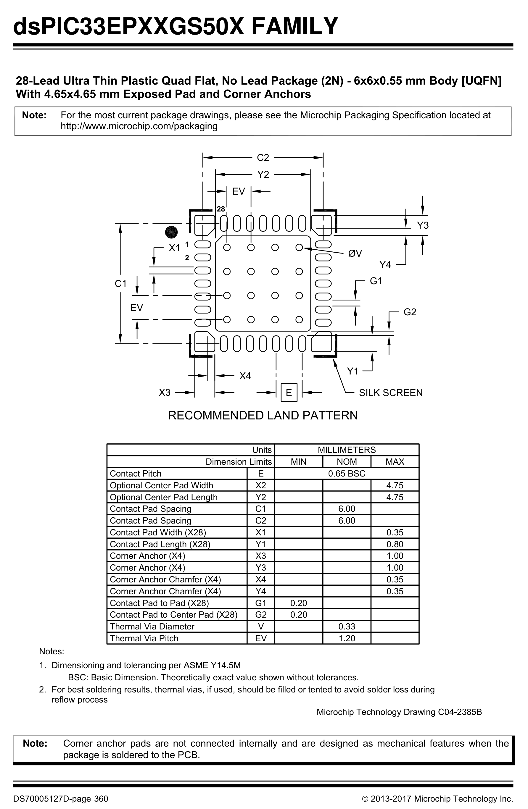
5. Recommended Land PatternLAND PATTERN
dsPIC33EP32GS505T-I/PT (TQFP-48-EP(7x7)) - 5. Recommended Land Pattern
IPC-7351B Footprint (48 Pads)Expand ›
6. Application SchematicSCHEMATIC
dsPIC33EP32GS505T-I/PT (TQFP-48-EP(7x7)) - 6. Application Schematic
Typical Application SchematicExpand ›
Original Datasheet Pinouts & Technical Drawings (14 figures · Page 1/2)
Showing 1–12 of 14 uncropped original figures for DSPIC33EP32G
P1 · p01_fig01377×200px
dsPIC33EP32GS505T-I/PT (TQFP-48-EP(7x7)) — 16-Bit Digital Signal Controllers for Digital Power Applications with Interconnected High-Speed PWM, ADC, PGA and Comparators
16-Bit Digital Signal Controllers for Digital Power Applications with Interconnected High-Speed PWM, ADC, PGA and Comparators
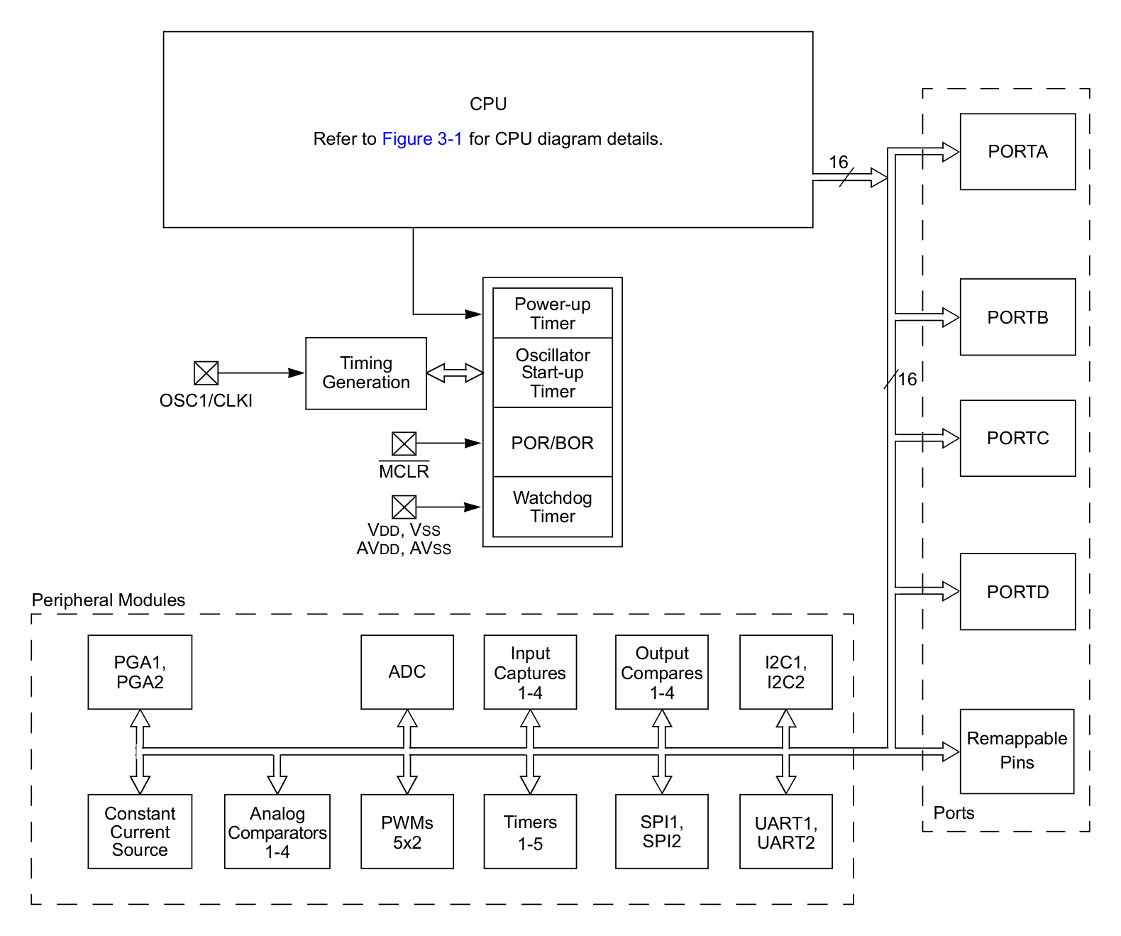
P11 · p11_fig011580×1319px
dsPIC33EP32GS505T-I/PT (TQFP-48-EP(7x7)) — FIGURE 1-1: dsPIC33EPXXGS50X FAMILY BLOCK DIAGRAM
FIGURE 1-1: dsPIC33EPXXGS50X FAMILY BLOCK DIAGRAM
P18 · p18_fig011456×1006px
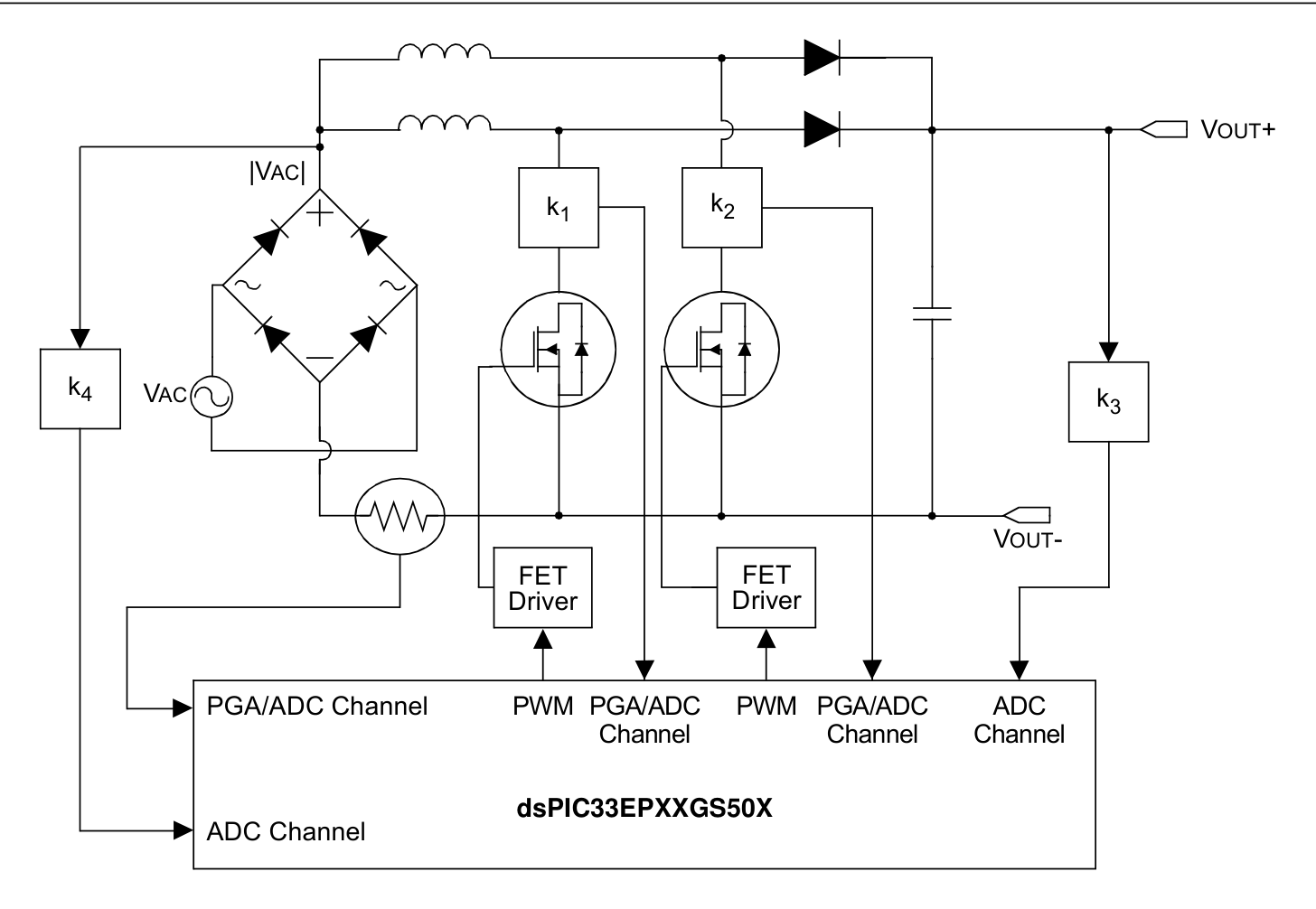
dsPIC33EP32GS505T-I/PT (TQFP-48-EP(7x7)) — FIGURE 2-4: INTERLEAVED PFC
FIGURE 2-4: INTERLEAVED PFC
P77 · p77_fig011777×969px
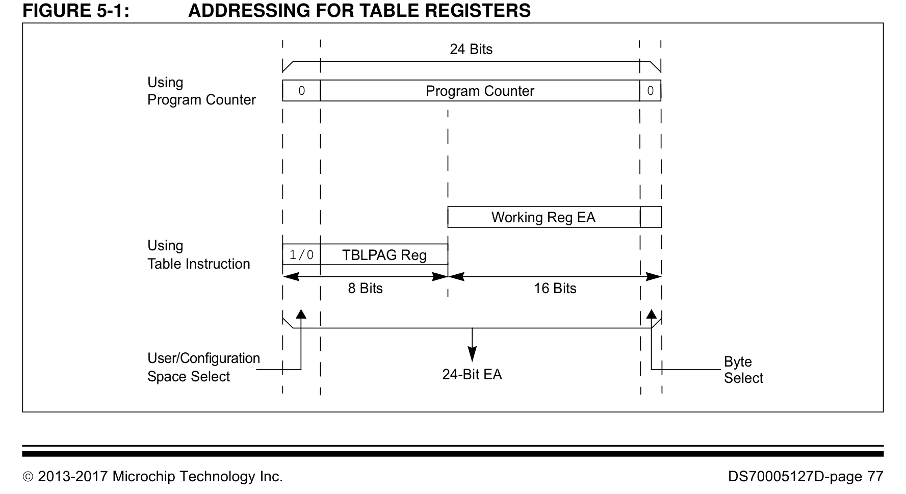
dsPIC33EP32GS505T-I/PT (TQFP-48-EP(7x7)) — FIGURE 5-1: ADDRESSING FOR TABLE REGISTERS
FIGURE 5-1: ADDRESSING FOR TABLE REGISTERS
P126 · p126_fig01874×366px
dsPIC33EP32GS505T-I/PT (TQFP-48-EP(7x7)) — MOV 0xFF00, W0 ; Configure PORTB<15:8> ; as inputs MOV W0, TRISB ; and PORTB<7:0> ; as outputs NOP ; Delay 1 cycle BTSS PORTB, #13 ; Next Instruction
MOV 0xFF00, W0 ; Configure PORTB<15:8> ; as inputs MOV W0, TRISB ; and PORTB<7:0> ; as outputs NOP ; Delay 1 cycle BTSS PORTB, #13 ; Next Instruction
P128 · p128_fig01867×999px
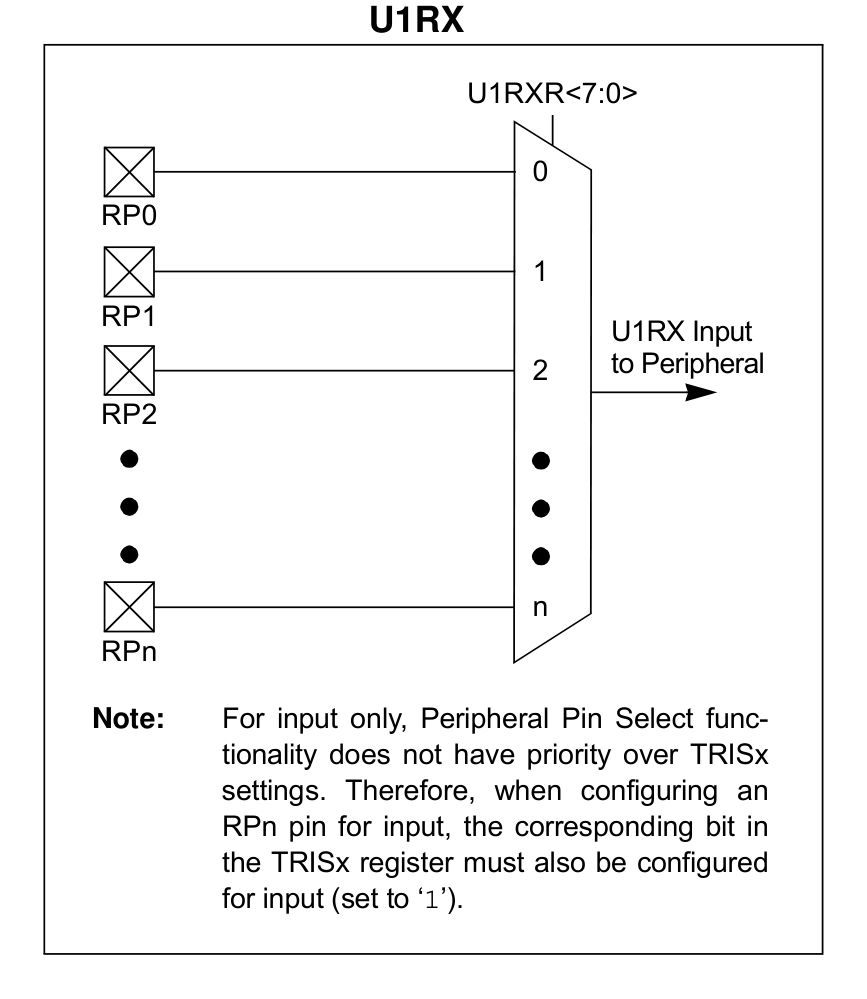
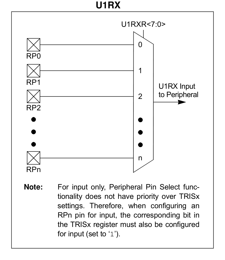
dsPIC33EP32GS505T-I/PT (TQFP-48-EP(7x7)) — FIGURE 10-2: REMAPPABLE INPUT FOR U1RX
FIGURE 10-2: REMAPPABLE INPUT FOR U1RX
P128 · p128_fig01P128
dsPIC33EP32GS505T-I/PT (TQFP-48-EP(7x7)) — Datasheet Page 128 (p128_fig01)
Datasheet Page 128 (p128_fig01)
P285 · p285_fig01867×874px
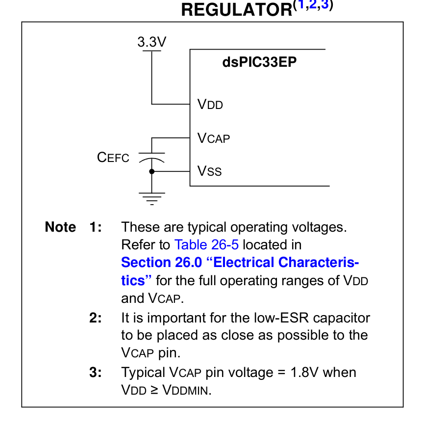
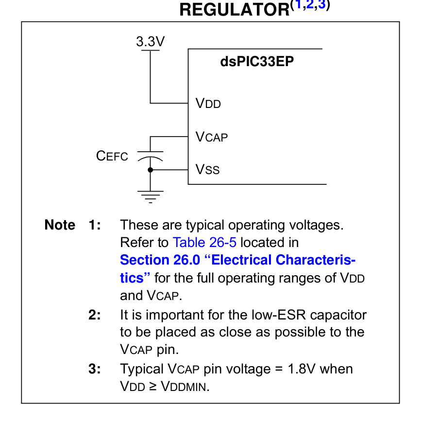
dsPIC33EP32GS505T-I/PT (TQFP-48-EP(7x7)) — FIGURE 23-1: CONNECTIONS FOR THE ON-CHIP VOLTAGE REGULATOR(1,2,3)
FIGURE 23-1: CONNECTIONS FOR THE ON-CHIP VOLTAGE REGULATOR(1,2,3)
P285 · p285_fig01P285
dsPIC33EP32GS505T-I/PT (TQFP-48-EP(7x7)) — Datasheet Page 285 (p285_fig01)
Datasheet Page 285 (p285_fig01)
P360 · p360_fig011784×2735px
dsPIC33EP32GS505T-I/PT (TQFP-48-EP(7x7)) — dsPIC33EPXXGS50X FAMILY | DS70005127D-page 360  2013-2017 Microchip Technology Inc. | RECOMMENDED LAND PATTERN | Dimension Limits | Units | C2 | Optional Center Pad Width | Contact Pad Spacing | Optional Center Pad Length | Contact Pitch |
dsPIC33EPXXGS50X FAMILY | DS70005127D-page 360  2013-2017 Microchip Technology Inc. | RECOMMENDED LAND PATTERN | Dimension Limits | Units | C2 | Optional Center Pad Width | Contact Pad Spacing | Optional Center Pad Length | Contact Pitch |
P369 · p369_fig011779×2735px
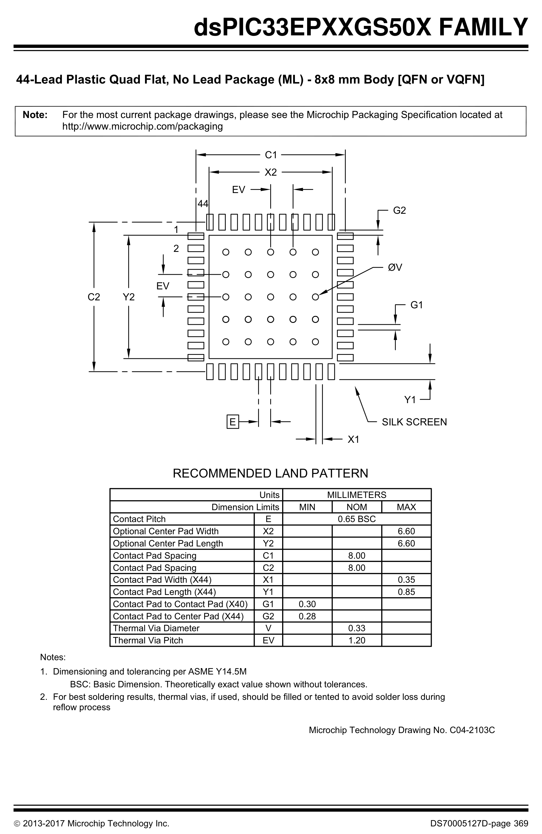
dsPIC33EP32GS505T-I/PT (TQFP-48-EP(7x7)) —  2013-2017 Microchip Technology Inc. DS70005127D-page 369 | dsPIC33EPXXGS50X FAMILY | RECOMMENDED LAND PATTERN | Dimension Limits | Units | C2 | Optional Center Pad Width | Contact Pad Spacing | Optional Center Pad Length | Contact Pitch |
 2013-2017 Microchip Technology Inc. DS70005127D-page 369 | dsPIC33EPXXGS50X FAMILY | RECOMMENDED LAND PATTERN | Dimension Limits | Units | C2 | Optional Center Pad Width | Contact Pad Spacing | Optional Center Pad Length | Contact Pitch |
P371 · p371_fig011779×2735px
dsPIC33EP32GS505T-I/PT (TQFP-48-EP(7x7)) — dsPIC33EPXXGS50X FAMILY - 48-Lead Thin Quad Flatpack (Y8) - 7x7x1.0 mm Body [TQFP] - http:/www.microchip.com/packaging |  2013-2017 Microchip Technology Inc. DS70005127D-page 371 | dsPIC33EPXXGS50X FAMILY | Microchip Technology Drawing C04
dsPIC33EPXXGS50X FAMILY - 48-Lead Thin Quad Flatpack (Y8) - 7x7x1.0 mm Body [TQFP] - http:/www.microchip.com/packaging |  2013-2017 Microchip Technology Inc. DS70005127D-page 371 | dsPIC33EPXXGS50X FAMILY | Microchip Technology Drawing C04
Page 1 / 2 (14 extracted figures)

Technical Specifications & Part Details (dsPIC33EP32GS505T-I/PT)

Summary of electrical parameters, mechanical dimensions, voltage range and peripheral interfaces from Datasheet (EN)
Standard Electronic & Interconnect Component
Detailed Overview:dsPIC33EP32GS505T-I/PT (TQFP-48-EP(7x7)) is a 48-pin standard electronic & interconnect component featuring a 7.00 × 7.00 × 1.20 mm mechanical envelope (lead pitch e = 0.50 mm). Rated for 3.0V to 3.6V supply operation across -40°C to +85°C with integrated UART, SPI, I2C, ADC, DAC, PWM, JTAG / SWD, IrDA, RTC/CLK interfaces.
Operating Supply VoltageV_CC / V_DD
3.0V to 3.6V
Place 100nF + 10µF X7R decoupling capacitors < 2mm from supply pins
Ambient Operating TemperatureT_A
-40°C to +85°C
Industrial temperature grade; T_J(max) = +125°C
Clock / RF Operating Frequencyf_CLK / f_RF
40 MHz
Extracted from authoritative PDF specification tables
Current & Power RatingI_OUT / I_CC
I_GPIO(max) = ±20 mA / pin | I_VDD(total) ≤ 150 mA
Observe per-pin absolute maximum current limits
Package Envelope (D × E × A)D × E × A
7.00 × 7.00 × 1.20 mm (A1=0.10 mm)
Package family: TQFP (TQFP-48-EP(7x7))
Pin Count & Lead PitchN / e
48 Pins | Pitch e = 0.50 mm (19.7 mil)
Normalized to Center-to-Center Span C per IPC-7351B
Integrated Peripheral InterfacesBuses
UART, SPI, I2C, ADC, DAC, PWM, JTAG / SWD, IrDA, RTC/CLK
Cross-linked with 4D Pinout & Schematic Symbol
Reflow & Moisture SensitivityIPC / MSL
IPC-7351B Level B | J-STD-020 (Peak 260°C) | MSL-3
60% windowed solder paste stencil on thermal EPAD
Engineering Safety Alert: Verify Pin-1 chamfer orientation on Top Silkscreen prior to SMT pick-and-place assembly.
Engineering Safety Alert: Connect exposed thermal pad (if present) to internal ground plane via 0.3mm stitched thermal vias.

5-Point Standards Verification

Automated compliance checks prior to export
5/5 PASS
IEEE-315 Symbol48 auto-grouped pins
OK
IPC-7351B Land Pattern48 pads · Pitch 0.50mm
OK
IPC-7525 60% Solder PasteReflow 1:1 Standard
OK
DFM Rules JLCPCB / PCBWayMin pad clearance: 0.25mm
OK
3D STEP AP214 & GLBAligned coordinate origin (0,0,0)
OK

Hardware Verification & Community Engineering Reviews

Summary of electrical parameters, mechanical dimensions, voltage range and peripheral interfaces from Datasheet
5.00 PCB Verified

Mechanical Dimensions & Land Pattern (TQFP-48-EP(7x7))

Extracted from Datasheet & IPC-7351B Normalized
mm
Package Body (D × E)Nominal
7.00 × 7.00 mm
Height (A) & Pitch (e)IPC-7351B
A=1.20mm · e=0.50mm
Pad Size (W × L)Level B
0.30 × 1.50 mm
Pins / Total PadsTopology
48P / 48Pad (QUAD_ROW)

Recommended Companion BOM & Drop-In Equivalents

Passive external components per reference schematic and 1:1 pin-compatible alternatives
DFM READY
Designator / Replacement MPNValue / PackageFunction & PCB Layout Rule
N/A
BOM
Per application circuit
TQFP-48-EP(7x7)
Size power & signal trace widths for rated load current following IPC-2221 clearance rules.

Technical Frequently Asked Questions (FAQ) — dsPIC33EP32GS505T-I/PT (TQFP-48-EP(7x7))

Quick answers covering Pinout, IPC-7351B Land Pattern dimensions, and CAD export formats
IPC-7351B / IEEE-315

What is the Pinout and operating voltage specification of dsPIC33EP32GS505T-I/PT (TQFP-48-EP(7x7))?

Manufactured by MICROCHIP, the dsPIC33EP32GS505T-I/PT is housed in a TQFP-48-EP(7x7) package with 48 pins and a 0.50 mm lead pitch, supporting a VCC supply range of 3.0V to 3.6V. Key pins include: 1 (TMS/ASDA1/RP41/RB9(4): Multiplexed I/O & Peripheral Pin TMS/ASDA1/RP41/RB9(4) (General)), 2 (RP54/RC6: Multiplexed I/O & Peripheral Pin RP54/RC6 (General)), 3 (RP55/RC7: Multiplexed I/O & Peripheral Pin RP55/RC7 (General)), 4 (RP56/RC8: Multiplexed I/O & Peripheral Pin RP56/RC8 (General)), 5 (RP57/RC9: Multiplexed I/O & Peripheral Pin RP57/RC9 (General)), 6 (VSS: Ground Reference Pin (VSS)).

What are the IPC-7351B PCB Footprint dimensions for dsPIC33EP32GS505T-I/PT?

Normalized from the official datasheet mechanical drawing per IPC-7351B (Density Level B Nominal), dsPIC33EP32GS505T-I/PT (TQFP-48-EP(7x7)) has a nominal body envelope of 7.00 × 7.00 mm, pitch e = 0.50 mm, and 48 copper pads.

Where can I download KiCad (.kicad_mod, .kicad_sym), Fusion 360 (.lbr), and 3D STEP models for dsPIC33EP32GS505T-I/PT?

You can download the verified open-hardware (CERN-OHL-P-2.0) CAD library bundle for dsPIC33EP32GS505T-I/PT (MICROCHIP, TQFP-48-EP(7x7)) directly on this page, including KiCad 8 Footprints (.kicad_mod), Schematic Symbols (.kicad_sym), Autodesk Fusion 360 / Eagle (.lbr), and 3D STEP AP214 / WebGL GLB models.

Static Reference Appendix: Pinout Table (48 pins) & DSPIC33EP32G Family VariantsExpand static table
Pin #Signal NameElectrical TypeFunctional Description & Design Notes
1TMS/ASDA1/RP41/RB9(4)Digital_IOSignal terminal TMS/ASDA1/RP41/RB9(4) (I/O, 3.0V to 3.6V domain). Multiplexed alternate functions: TMS/ASDA1/RP41/RB9(4). Supported peripheral buses: General.
2RP54/RC6Digital_IOSignal terminal RP54/RC6 (I/O, 3.0V to 3.6V domain). Multiplexed alternate functions: RP54/RC6. Supported peripheral buses: General.
3RP55/RC7Digital_IOSignal terminal RP55/RC7 (I/O, 3.0V to 3.6V domain). Multiplexed alternate functions: RP55/RC7. Supported peripheral buses: General.
4RP56/RC8Digital_IOSignal terminal RP56/RC8 (I/O, 3.0V to 3.6V domain). Multiplexed alternate functions: RP56/RC8. Supported peripheral buses: General.
5RP57/RC9Digital_IOSignal terminal RP57/RC9 (I/O, 3.0V to 3.6V domain). Multiplexed alternate functions: RP57/RC9. Supported peripheral buses: General.
6VSSGND0V electrical ground return terminal (VSS) for internal core logic, I/O drivers, and analog sub-blocks.
7VCAPDigital_IOSignal terminal VCAP (I/O, 3.0V to 3.6V domain). Multiplexed alternate functions: VCAP. Supported peripheral buses: General.
8N/CDigital_IOSignal terminal N/C (I/O, 3.0V to 3.6V domain). Multiplexed alternate functions: N/C. Supported peripheral buses: General.
9RP42/PWM3H/RB10Digital_IOSignal terminal RP42/PWM3H/RB10 (I/O, 3.0V to 3.6V domain). Multiplexed alternate functions: RP42/PWM3H/RB10. Supported peripheral buses: PWM.
10RP43/PWM3L/RB11Digital_IOSignal terminal RP43/PWM3L/RB11 (I/O, 3.0V to 3.6V domain). Multiplexed alternate functions: RP43/PWM3L/RB11. Supported peripheral buses: PWM.
11RPI44/PWM2H/RB12Digital_IOSignal terminal RPI44/PWM2H/RB12 (I/O, 3.0V to 3.6V domain). Multiplexed alternate functions: RPI44/PWM2H/RB12. Supported peripheral buses: PWM.
12RPI45/PWM2L/CTPLS/RB13Digital_IOSignal terminal RPI45/PWM2L/CTPLS/RB13 (I/O, 3.0V to 3.6V domain). Multiplexed alternate functions: RPI45/PWM2L/CTPLS/RB13. Supported peripheral buses: PWM.
13TDO/RA10Digital_IOSignal terminal TDO/RA10 (I/O, 3.0V to 3.6V domain). Multiplexed alternate functions: TDO/RA10. Supported peripheral buses: General.
14TDI/RA7Digital_IOSignal terminal TDI/RA7 (I/O, 3.0V to 3.6V domain). Multiplexed alternate functions: TDI/RA7. Supported peripheral buses: General.
15RPI46/PWM1H/T3CK/RB14Digital_IOSignal terminal RPI46/PWM1H/T3CK/RB14 (I/O, 3.0V to 3.6V domain). Multiplexed alternate functions: RPI46/PWM1H/T3CK/RB14. Supported peripheral buses: PWM.
16RPI47/PWM1L/T5CK/RB15Digital_IOSignal terminal RPI47/PWM1L/T5CK/RB15 (I/O, 3.0V to 3.6V domain). Multiplexed alternate functions: RPI47/PWM1L/T5CK/RB15. Supported peripheral buses: PWM.
17AVSSGND0V electrical ground return terminal (AVSS) for internal core logic, I/O drivers, and analog sub-blocks.
18AVDDPower_InPrimary positive power supply input (AVDD) operating in the 3.0V to 3.6V domain (Max rating: 3.6V).
19MCLR#Digital_IOSignal terminal MCLR# (I/O, 3.0V to 3.6V domain). Multiplexed alternate functions: MCLR#. Supported peripheral buses: General.
20N/CDigital_IOSignal terminal N/C (I/O, 3.0V to 3.6V domain). Multiplexed alternate functions: N/C. Supported peripheral buses: General.
21AN0/OA2OUT/RA0Digital_IOSignal terminal AN0/OA2OUT/RA0 (I/O, 3.0V to 3.6V domain). Multiplexed alternate functions: AN0/OA2OUT/RA0. Supported peripheral buses: General.
22AN1/C2IN1+/RA1Digital_IOSignal terminal AN1/C2IN1+/RA1 (I/O, 3.0V to 3.6V domain). Multiplexed alternate functions: AN1/C2IN1+/RA1. Supported peripheral buses: General.
23IO12Digital_IOGPIO12 / RTC_GPIO12 / TOUCH12 / ADC2_CH1 / FSPICLK
24IO13Digital_IOGPIO13 / RTC_GPIO13 / TOUCH13 / ADC2_CH2 / FSPIQ
25IO14Digital_IOGPIO14 / RTC_GPIO14 / TOUCH14 / ADC2_CH3 / FSPIWP
26IO21Digital_IOGPIO21 / RTC_GPIO21
27IO47Digital_IOGPIO47 / SPICLK_P_DIFF / SUBSPICLK_P_DIFF
28AN7/C3IN1-/C4IN1-/RC1Digital_IOSignal terminal AN7/C3IN1-/C4IN1-/RC1 (I/O, 3.0V to 3.6V domain). Multiplexed alternate functions: AN7/C3IN1-/C4IN1-/RC1. Supported peripheral buses: General.
29IO29Digital_IOGeneral Purpose Digital I/O Pin IO29
30VDDPower_InPrimary positive power supply input (VDD) operating in the 3.0V to 3.6V domain (Max rating: 3.6V).
31VSSGND0V electrical ground return terminal (VSS) for internal core logic, I/O drivers, and analog sub-blocks.
32N/CDigital_IOSignal terminal N/C (I/O, 3.0V to 3.6V domain). Multiplexed alternate functions: N/C. Supported peripheral buses: General.
33OSC1/CLKI/RA2Digital_IOSignal terminal OSC1/CLKI/RA2 (I/O, 3.0V to 3.6V domain). Multiplexed alternate functions: OSC1/CLKI/RA2. Supported peripheral buses: RTC/CLK.
34OSC2/CLKO/RA3Digital_IOSignal terminal OSC2/CLKO/RA3 (I/O, 3.0V to 3.6V domain). Multiplexed alternate functions: OSC2/CLKO/RA3. Supported peripheral buses: RTC/CLK.
35SDA2/RPI24/RA8Digital_IOSignal terminal SDA2/RPI24/RA8 (I/O, 3.0V to 3.6V domain). Multiplexed alternate functions: SDA2/RPI24/RA8. Supported peripheral buses: I2C.
36FLT32/SCL2/RP36/RB4Digital_IOSignal terminal FLT32/SCL2/RP36/RB4 (I/O, 3.0V to 3.6V domain). Multiplexed alternate functions: FLT32/SCL2/RP36/RB4. Supported peripheral buses: I2C.
37IO37Digital_IOGeneral Purpose Digital I/O Pin IO37
38SDI1/RPI25/RA9Digital_IOSignal terminal SDI1/RPI25/RA9 (I/O, 3.0V to 3.6V domain). Multiplexed alternate functions: SDI1/RPI25/RA9. Supported peripheral buses: General.
39SCK1/RPI51/RC3Digital_IOSignal terminal SCK1/RPI51/RC3 (I/O, 3.0V to 3.6V domain). Multiplexed alternate functions: SCK1/RPI51/RC3. Supported peripheral buses: SPI.
40SDA1/RPI52/RC4Digital_IOSignal terminal SDA1/RPI52/RC4 (I/O, 3.0V to 3.6V domain). Multiplexed alternate functions: SDA1/RPI52/RC4. Supported peripheral buses: I2C.
41SCL1/RPI53/RC5Digital_IOSignal terminal SCL1/RPI53/RC5 (I/O, 3.0V to 3.6V domain). Multiplexed alternate functions: SCL1/RPI53/RC5. Supported peripheral buses: I2C.
42VSSGND0V electrical ground return terminal (VSS) for internal core logic, I/O drivers, and analog sub-blocks.
43VDDPower_InPrimary positive power supply input (VDD) operating in the 3.0V to 3.6V domain (Max rating: 3.6V).
44N/CDigital_IOSignal terminal N/C (I/O, 3.0V to 3.6V domain). Multiplexed alternate functions: N/C. Supported peripheral buses: General.
45PGED2/ASDA2/RP37/RB5Digital_IOSignal terminal PGED2/ASDA2/RP37/RB5 (I/O, 3.0V to 3.6V domain). Multiplexed alternate functions: PGED2/ASDA2/RP37/RB5. Supported peripheral buses: General.
46PGEC2/ASCL2/RP38/RB6Digital_IOSignal terminal PGEC2/ASCL2/RP38/RB6 (I/O, 3.0V to 3.6V domain). Multiplexed alternate functions: PGEC2/ASCL2/RP38/RB6. Supported peripheral buses: General.
47RP39/INT0/RB7Digital_IOSignal terminal RP39/INT0/RB7 (I/O, 3.0V to 3.6V domain). Multiplexed alternate functions: RP39/INT0/RB7. Supported peripheral buses: General.
48IO48Digital_IOGeneral Purpose Digital I/O Pin IO48