
MCP6549T-E/SL (SOIC-14) — Symbol, Footprint IPC-7351B & 3D STEP Model

MCP6549T-E/SL

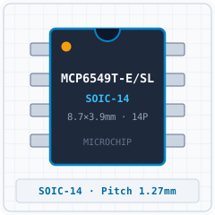
MICROCHIPSOIC-14 · 14 Pins · Pitch 1.27mmIPC TOLERANCE VARIATION5.0 (0)
SYNCHRONIZED 4D CROSS-PROBE MODETouch or hover any pin to highlight concurrently across Symbol, Footprint and 3D
1. SYMBOL
U1 · MCP6549T-E/SL (SOIC-14)1NC2V –, IN V – 3V +, IN V + 4VSS5NC6OUT, OUTA7VDD14OUTD13VIND–12VIND+11VSS10VINC+9VINC–8NCGrid Pitch = 2.54mm (IEEE-315)-17.8-12.7-7.6-2.52.57.612.717.815.210.25.10-5.1-10.2-15.2mm
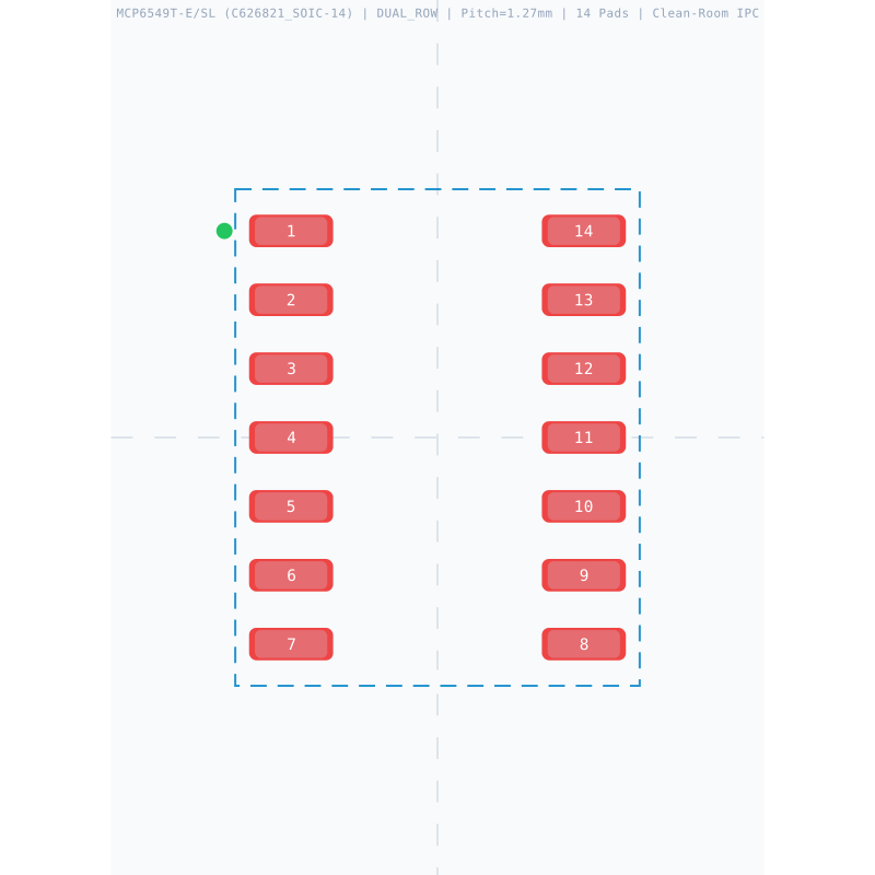
2. 2D FOOTPRINT
1234567891011121314E=3.90mm · Pitch e=1.27mmD=8.65mm-5-4-3-2-10123456543210-1-2-3-4-5-6mm
3. 3D CAD MODEL
Package Body: 3.90mm × 8.65mm · Pitch: 1.27mm · Ruler Step: 1.00mmSynced <100ms

Synchronized Pinout (Symbol / 2D / 3D) (14/14)

Touch or hover any pin to highlight concurrently across Symbol, Footprint and 3D
PinSymbolTypeFunction (EN)
1NCI/OMultiplexed I/O & Peripheral Pin NC (General)
2V –, IN V – INAI/OMultiplexed I/O & Peripheral Pin V –, IN V – INA (General)
3V +, IN V + INAI/OMultiplexed I/O & Peripheral Pin V +, IN V + INA (General)
4VSSGNDGround Reference Pin (VSS)
5NCI/OMultiplexed I/O & Peripheral Pin NC (General)
6OUT, OUTAI/OMultiplexed I/O & Peripheral Pin OUT, OUTA (General)
7VDDPowerPower Supply Input (VDD — 1.6V to 5.5V)
8NCI/OMultiplexed I/O & Peripheral Pin NC (General)
9VINC–PowerPower Supply Input (VINC– — 1.6V to 5.5V)
10VINC+PowerPower Supply Input (VINC+ — 1.6V to 5.5V)
11VSSGNDGround Reference Pin (VSS)
12VIND+PowerPower Supply Input (VIND+ — 1.6V to 5.5V)
13VIND–PowerPower Supply Input (VIND– — 1.6V to 5.5V)
14OUTDI/OMultiplexed I/O & Peripheral Pin OUTD (General)
PIN 1 NC
I/O
Multiplexed I/O & Peripheral Pin NC (General)
Design note: No Internal Connection
IPC-7351B Solder Density & Span C/G/Z Tuner

Extracted Drawings Gallery (6 Standard Drawings + 20 Extracted Figures)

Read the original datasheet PDF directly or click any drawing to view fullscreen
1. Realistic 3D PackageREPRESENTATIVE
MCP6549T-E/SL (SOIC-14) - 1. Realistic 3D Package
Detailed solid 3D bodyExpand ›
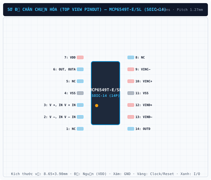
2. Standard Pinout (Top View)CLEANROOM PINOUT
MCP6549T-E/SL (SOIC-14) - 2. Standard Pinout (Top View)
True package pinout (14 pins)Expand ›
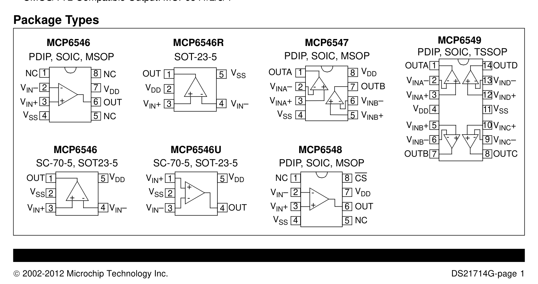
3. Original Datasheet PinoutPDF PINOUT
MCP6549T-E/SL (SOIC-14) - 3. Original Datasheet Pinout
Uncropped datasheet pin diagramExpand ›
4. Package Dimensions (D×E×A)PACKAGE DIMENSIONS
MCP6549T-E/SL (SOIC-14) - 4. Package Dimensions (D×E×A)
SOIC-14 · 3.90×8.65mm · Pitch 1.27mmExpand ›
5. Recommended Land PatternLAND PATTERN
MCP6549T-E/SL (SOIC-14) - 5. Recommended Land Pattern
IPC-7351B Footprint (14 Pads)Expand ›
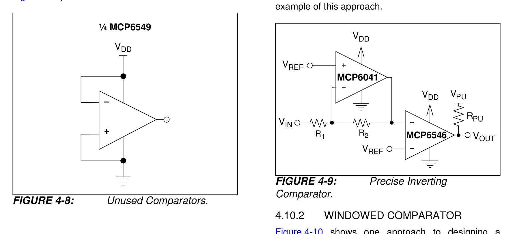
6. Application SchematicSCHEMATIC
MCP6549T-E/SL (SOIC-14) - 6. Application Schematic
Typical Application SchematicExpand ›
Original Datasheet Pinouts & Technical Drawings (20 figures · Page 1/2)
Showing 1–12 of 20 uncropped original figures for MCP6549
P1 · p01_fig01377×200px
MCP6549T-E/SL (SOIC-14) — Open-Drain Output Sub-Microamp Comparators
Open-Drain Output Sub-Microamp Comparators
P1 · p01_fig021777×939px
MCP6549T-E/SL (SOIC-14) — • CMOS/TTL-Compatible Output: MCP6541/2/3/4 MCP6541 MCP6542 MCP6543 MCP6544
• CMOS/TTL-Compatible Output: MCP6541/2/3/4 MCP6541 MCP6542 MCP6543 MCP6544
P6 · p06_fig011777×607px
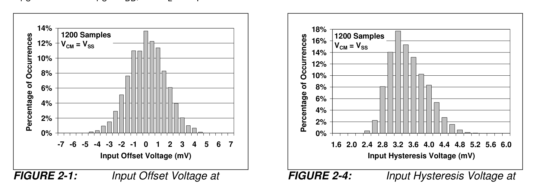
MCP6549T-E/SL (SOIC-14) — FIGURE 2-4: Input Hysteresis Voltage at VCM = VSS.
FIGURE 2-4: Input Hysteresis Voltage at VCM = VSS.
P6 · p06_fig021777×608px
MCP6549T-E/SL (SOIC-14) — FIGURE 2-1: Input Offset Voltage at VCM = VSS.
FIGURE 2-1: Input Offset Voltage at VCM = VSS.
P6 · p06_fig031777×608px
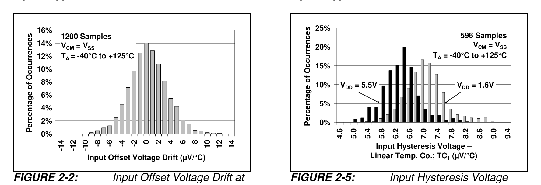
MCP6549T-E/SL (SOIC-14) — FIGURE 2-2: Input Offset Voltage Drift at VCM = VSS.
FIGURE 2-2: Input Offset Voltage Drift at VCM = VSS.
P18 · p18_fig011777×811px
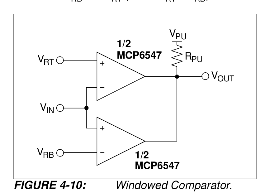
MCP6549T-E/SL (SOIC-14) — Figure 4-10 shows one approach to designing a windowed comparator. The wired-OR connection produces a high output (logic 1) when the input voltage is between VRB and VRT (where VRT > VRB).
Figure 4-10 shows one approach to designing a windowed comparator. The wired-OR connection produces a high output (logic 1) when the input voltage is between VRB and VRT (where VRT > VRB).
P18 · p18_fig02867×619px
MCP6549T-E/SL (SOIC-14) — Figure 4-10 shows one approach to designing a windowed comparator. The wired-OR connection produces a high output (logic 1) when the input voltage is between VRB and VRT (where VRT > VRB).
Figure 4-10 shows one approach to designing a windowed comparator. The wired-OR connection produces a high output (logic 1) when the input voltage is between VRB and VRT (where VRT > VRB).
P18 · p18_fig01P18
MCP6549T-E/SL (SOIC-14) — Datasheet Page 18 (p18_fig01)
Datasheet Page 18 (p18_fig01)
P19 · p19_fig11263×309px
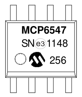
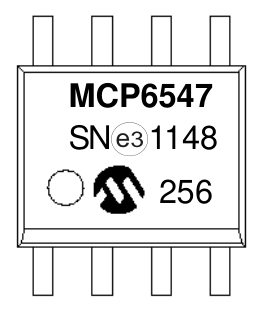
MCP6549T-E/SL (SOIC-14) — MCP6547 MCP6547 I/SN1148 | 256 256 | S N ^^1148 3 e
MCP6547 MCP6547 I/SN1148 | 256 256 | S N ^^1148 3 e
P19 · p19_fig11P19
MCP6549T-E/SL (SOIC-14) — Datasheet Page 19 (p19_fig11)
Datasheet Page 19 (p19_fig11)
P19 · p19_fig01All Packages in PDF
MCP6549T-E/SL (SOIC-14) — 5.0 PACKAGING INFORMATION
5.0 PACKAGING INFORMATION
P19 · p19_fig02All Packages in PDF
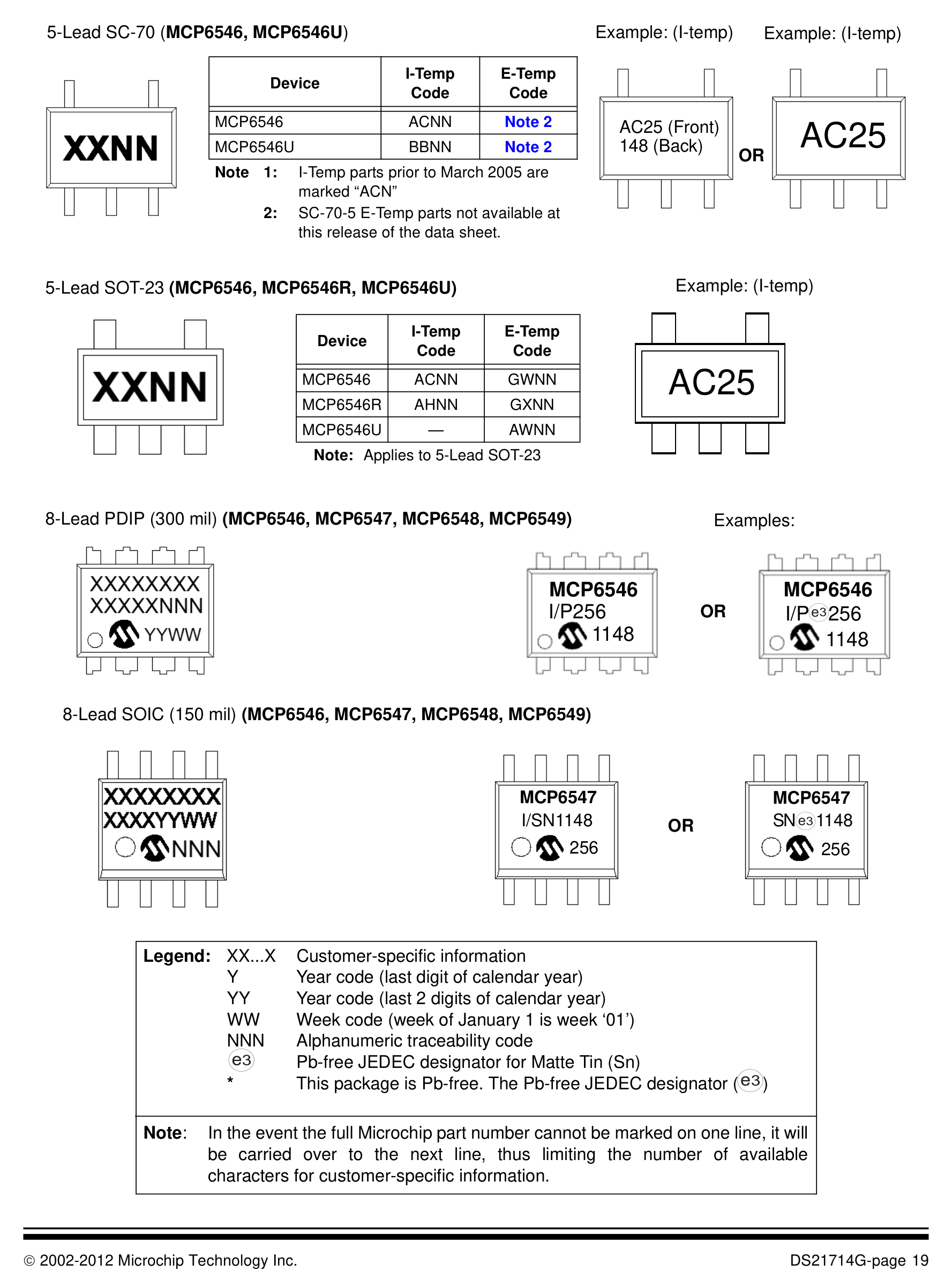
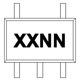
MCP6549T-E/SL (SOIC-14) — 5.1 Package Marking Information 5-Lead SC-70 (MCP6546, MCP6546U) Example: (I-temp)
5.1 Package Marking Information 5-Lead SC-70 (MCP6546, MCP6546U) Example: (I-temp)
Page 1 / 2 (20 extracted figures)

Technical Specifications & Part Details (MCP6549T-E/SL)

Summary of electrical parameters, mechanical dimensions, voltage range and peripheral interfaces from Datasheet (EN)
Standard Electronic & Interconnect Component
Detailed Overview:MCP6549T-E/SL (SOIC-14) is a 14-pin standard electronic & interconnect component featuring a 8.65 × 3.90 × 1.75 mm mechanical envelope (lead pitch e = 1.27 mm). Rated for 1.6V to 5.5V supply operation across -40°C to +85°C with integrated Standard I/O / Passive interfaces.
Operating Supply VoltageV_CC / V_DD
1.6V to 5.5V
Place 100nF + 10µF X7R decoupling capacitors < 2mm from supply pins
Ambient Operating TemperatureT_A
-40°C to +85°C
Industrial temperature grade; T_J(max) = +125°C
Clock / RF Operating Frequencyf_CLK / f_RF
100 kHz
Extracted from authoritative PDF specification tables
Current & Power RatingI_OUT / I_CC
30 mA
Observe per-pin absolute maximum current limits
Package Envelope (D × E × A)D × E × A
8.65 × 3.90 × 1.75 mm (A1=0.15 mm)
Package family: SOIC (SOIC-14)
Pin Count & Lead PitchN / e
14 Pins | Pitch e = 1.27 mm (50.0 mil)
Normalized to Center-to-Center Span C per IPC-7351B
Integrated Peripheral InterfacesBuses
Standard I/O / Passive
Cross-linked with 4D Pinout & Schematic Symbol
Reflow & Moisture SensitivityIPC / MSL
IPC-7351B Level B | J-STD-020 (Peak 260°C) | MSL-3
60% windowed solder paste stencil on thermal EPAD
Engineering Safety Alert: Verify Pin-1 chamfer orientation on Top Silkscreen prior to SMT pick-and-place assembly.
Engineering Safety Alert: Connect exposed thermal pad (if present) to internal ground plane via 0.3mm stitched thermal vias.

5-Point Standards Verification

Automated compliance checks prior to export
5/5 PASS
IEEE-315 Symbol14 auto-grouped pins
OK
IPC-7351B Land Pattern14 pads · Pitch 1.27mm
OK
IPC-7525 60% Solder PasteReflow 1:1 Standard
OK
DFM Rules JLCPCB / PCBWayMin pad clearance: 0.25mm
OK
3D STEP AP214 & GLBAligned coordinate origin (0,0,0)
OK

Hardware Verification & Community Engineering Reviews

Summary of electrical parameters, mechanical dimensions, voltage range and peripheral interfaces from Datasheet
5.00 PCB Verified

Mechanical Dimensions & Land Pattern (SOIC-14)

Extracted from Datasheet & IPC-7351B Normalized
mm
Package Body (D × E)Nominal
8.65 × 3.90 mm
Height (A) & Pitch (e)IPC-7351B
A=1.75mm · e=1.27mm
Pad Size (W × L)Level B
0.60 × 1.55 mm
Pins / Total PadsTopology
14P / 14Pad (DUAL_ROW)

Recommended Companion BOM & Drop-In Equivalents

Passive external components per reference schematic and 1:1 pin-compatible alternatives
DFM READY
Designator / Replacement MPNValue / PackageFunction & PCB Layout Rule
N/A
BOM
Per application circuit
SOIC-14
Size power & signal trace widths for rated load current following IPC-2221 clearance rules.

Technical Frequently Asked Questions (FAQ) — MCP6549T-E/SL (SOIC-14)

Quick answers covering Pinout, IPC-7351B Land Pattern dimensions, and CAD export formats
IPC-7351B / IEEE-315

What is the Pinout and operating voltage specification of MCP6549T-E/SL (SOIC-14)?

Manufactured by MICROCHIP, the MCP6549T-E/SL is housed in a SOIC-14 package with 14 pins and a 1.27 mm lead pitch, supporting a VCC supply range of 1.6V to 5.5V. Key pins include: 1 (NC: Multiplexed I/O & Peripheral Pin NC (General)), 2 (V –, IN V – INA: Multiplexed I/O & Peripheral Pin V –, IN V – INA (General)), 3 (V +, IN V + INA: Multiplexed I/O & Peripheral Pin V +, IN V + INA (General)), 4 (VSS: Ground Reference Pin (VSS)), 5 (NC: Multiplexed I/O & Peripheral Pin NC (General)), 6 (OUT, OUTA: Multiplexed I/O & Peripheral Pin OUT, OUTA (General)).

What are the IPC-7351B PCB Footprint dimensions for MCP6549T-E/SL?

Normalized from the official datasheet mechanical drawing per IPC-7351B (Density Level B Nominal), MCP6549T-E/SL (SOIC-14) has a nominal body envelope of 3.90 × 8.65 mm, pitch e = 1.27 mm, and 14 copper pads.

Where can I download KiCad (.kicad_mod, .kicad_sym), Fusion 360 (.lbr), and 3D STEP models for MCP6549T-E/SL?

You can download the verified open-hardware (CERN-OHL-P-2.0) CAD library bundle for MCP6549T-E/SL (MICROCHIP, SOIC-14) directly on this page, including KiCad 8 Footprints (.kicad_mod), Schematic Symbols (.kicad_sym), Autodesk Fusion 360 / Eagle (.lbr), and 3D STEP AP214 / WebGL GLB models.

Static Reference Appendix: Pinout Table (14 pins) & MCP6549 Family VariantsExpand static table
Pin #Signal NameElectrical TypeFunctional Description & Design Notes
1NCNCSignal terminal NC (I/O, 1.6V to 5.5V domain). Multiplexed alternate functions: NC. Supported peripheral buses: General.
2V –, IN V – INADigital_IOSignal terminal V –, IN V – INA (I/O, 1.6V to 5.5V domain). Multiplexed alternate functions: V –, IN V – INA. Supported peripheral buses: General.
3V +, IN V + INADigital_IOSignal terminal V +, IN V + INA (I/O, 1.6V to 5.5V domain). Multiplexed alternate functions: V +, IN V + INA. Supported peripheral buses: General.
4VSSGND0V electrical ground return terminal (VSS) for internal core logic, I/O drivers, and analog sub-blocks.
5NCNCSignal terminal NC (I/O, 1.6V to 5.5V domain). Multiplexed alternate functions: NC. Supported peripheral buses: General.
6OUT, OUTADigital_IOSignal terminal OUT, OUTA (I/O, 1.6V to 5.5V domain). Multiplexed alternate functions: OUT, OUTA. Supported peripheral buses: General.
7VDDPower_InPrimary positive power supply input (VDD) operating in the 1.6V to 5.5V domain (Max rating: 5.5V).
8NCNCSignal terminal NC (I/O, 1.6V to 5.5V domain). Multiplexed alternate functions: NC. Supported peripheral buses: General.
9VINC–Power_InPrimary positive power supply input (VINC–) operating in the 1.6V to 5.5V domain (Max rating: 5.5V).
10VINC+Power_InPrimary positive power supply input (VINC+) operating in the 1.6V to 5.5V domain (Max rating: 5.5V).
11VSSGND0V electrical ground return terminal (VSS) for internal core logic, I/O drivers, and analog sub-blocks.
12VIND+Power_InPrimary positive power supply input (VIND+) operating in the 1.6V to 5.5V domain (Max rating: 5.5V).
13VIND–Power_InPrimary positive power supply input (VIND–) operating in the 1.6V to 5.5V domain (Max rating: 5.5V).
14OUTDDigital_IOSignal terminal OUTD (I/O, 1.6V to 5.5V domain). Multiplexed alternate functions: OUTD. Supported peripheral buses: General.