
PIC16F1828T-I/SS (SSOP-20-208mil) — Symbol, Footprint IPC-7351B & 3D STEP Model

PIC16F1828T-I/SS

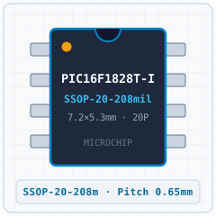
MICROCHIPSSOP-20-208mil · 20 Pins · Pitch 0.65mmIPC TOLERANCE VARIATION5.0 (0)
SYNCHRONIZED 4D CROSS-PROBE MODETouch or hover any pin to highlight concurrently across Symbol, Footprint and 3D
1. SYMBOL
U1 · PIC16F1828T-I/SS (SSOP-20-208mil)1VDD2RA53RA44RA3/MCLR#/VP5RC56RC47RC38RC69RC710RB720VSS19RA0/ICSPDAT18RA1/ICSPCLK17RA216RC015RC114RC213RB412RB511RB6Grid Pitch = 2.54mm (IEEE-315)-17.8-12.7-7.6-2.52.57.612.717.817.812.77.62.5-2.5-7.6-12.7-17.8mm
2. 2D FOOTPRINT
1234567891011121314151617181920E=5.30mm · Pitch e=0.65mmD=7.20mm-6-5-4-3-2-101234566543210-1-2-3-4-5-6mm
3. 3D CAD MODEL
Package Body: 5.30mm × 7.20mm · Pitch: 0.65mm · Ruler Step: 1.00mmSynced <100ms

Synchronized Pinout (Symbol / 2D / 3D) (20/20)

Touch or hover any pin to highlight concurrently across Symbol, Footprint and 3D
PinSymbolTypeFunction (EN)
1VDDPowerPower Supply Input (VDD — 1.8V-5.5V)
2RA5I/OMultiplexed I/O & Peripheral Pin RA5 (General)
3RA4I/OMultiplexed I/O & Peripheral Pin RA4 (General)
4RA3/MCLR#/VPPI/OMultiplexed I/O & Peripheral Pin RA3/MCLR#/VPP (General)
5RC5I/OMultiplexed I/O & Peripheral Pin RC5 (General)
6RC4I/OMultiplexed I/O & Peripheral Pin RC4 (General)
7RC3I/OMultiplexed I/O & Peripheral Pin RC3 (General)
8RC6I/OMultiplexed I/O & Peripheral Pin RC6 (General)
9RC7I/OMultiplexed I/O & Peripheral Pin RC7 (General)
10RB7I/OMultiplexed I/O & Peripheral Pin RB7 (General)
11RB6I/OMultiplexed I/O & Peripheral Pin RB6 (General)
12RB5I/OMultiplexed I/O & Peripheral Pin RB5 (General)
13RB4I/OMultiplexed I/O & Peripheral Pin RB4 (General)
14RC2I/OMultiplexed I/O & Peripheral Pin RC2 (General)
15RC1I/OMultiplexed I/O & Peripheral Pin RC1 (General)
16RC0I/OMultiplexed I/O & Peripheral Pin RC0 (General)
17RA2I/OMultiplexed I/O & Peripheral Pin RA2 (General)
18RA1/ICSPCLKI/OMultiplexed I/O & Peripheral Pin RA1/ICSPCLK (General)
19RA0/ICSPDATI/OMultiplexed I/O & Peripheral Pin RA0/ICSPDAT (General)
20VSSGNDGround Reference Pin (VSS)
PIN 1 VDD
Power
Power Supply Input (VDD — 1.8V-5.5V)
Design note: Primary positive power supply input (VDD) operating in the 1.8V-5.5V domain (Max rating: 5.5V).
IPC-7351B Solder Density & Span C/G/Z Tuner

Extracted Drawings Gallery (6 Standard Drawings + 16 Extracted Figures)

Read the original datasheet PDF directly or click any drawing to view fullscreen
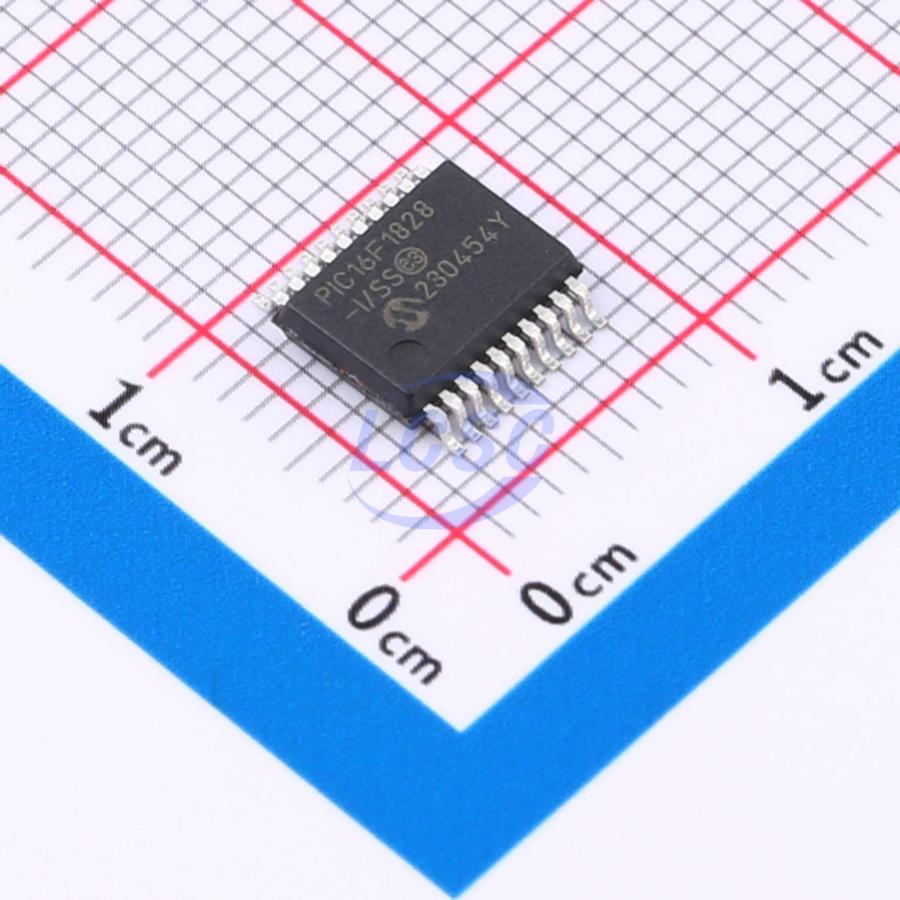
1. Realistic 3D PackageREPRESENTATIVE
PIC16F1828T-I/SS (SSOP-20-208mil) - 1. Realistic 3D Package
Detailed solid 3D bodyExpand ›
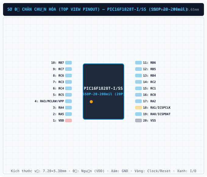
2. Standard Pinout (Top View)CLEANROOM PINOUT
PIC16F1828T-I/SS (SSOP-20-208mil) - 2. Standard Pinout (Top View)
True package pinout (20 pins)Expand ›
3. Original Datasheet PinoutPDF PINOUT
PIC16F1828T-I/SS (SSOP-20-208mil) - 3. Original Datasheet Pinout
Uncropped datasheet pin diagramExpand ›
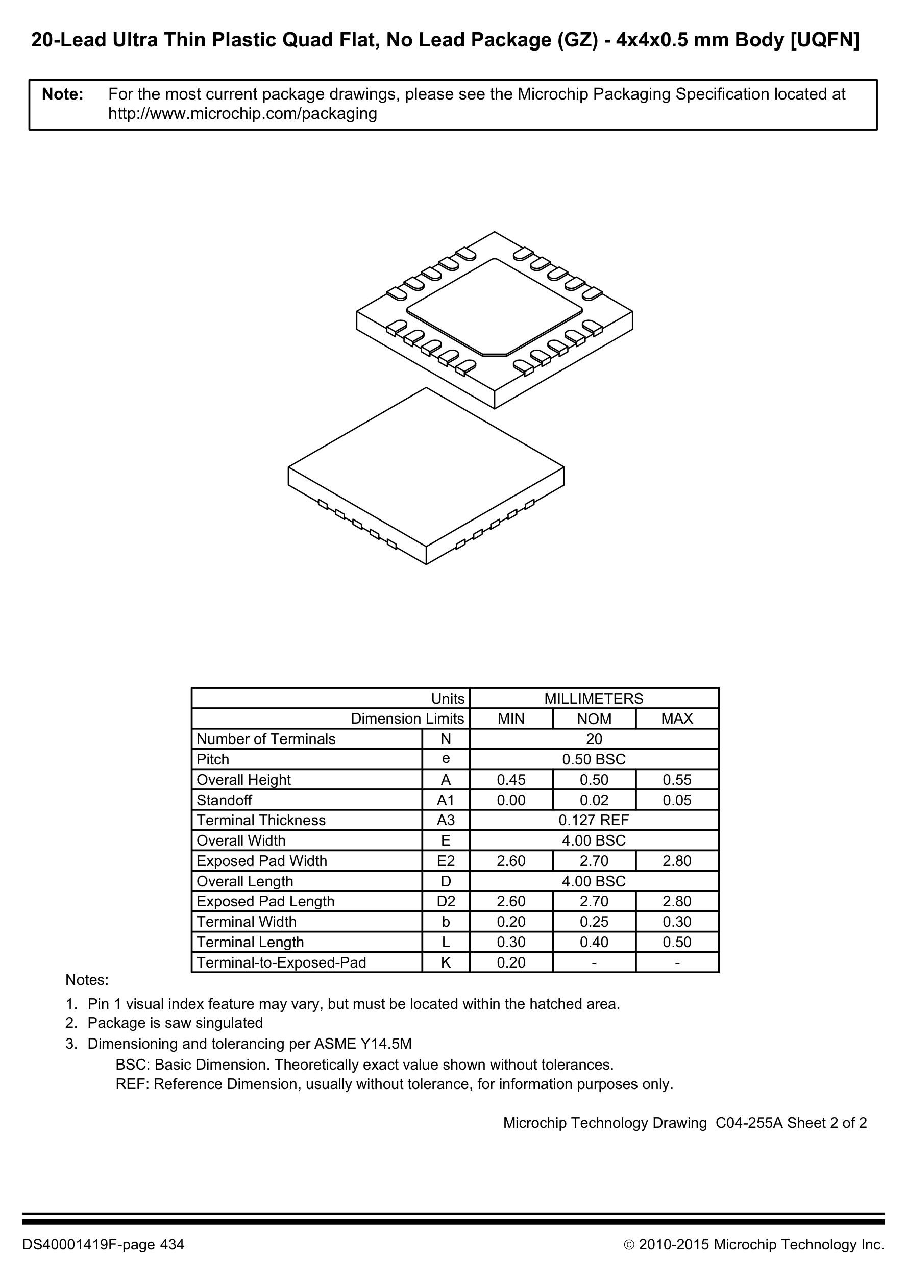
4. Package Dimensions (D×E×A)PACKAGE DIMENSIONS
PIC16F1828T-I/SS (SSOP-20-208mil) - 4. Package Dimensions (D×E×A)
SSOP-20-208mil · 5.30×7.20mm · Pitch 0.65mmExpand ›
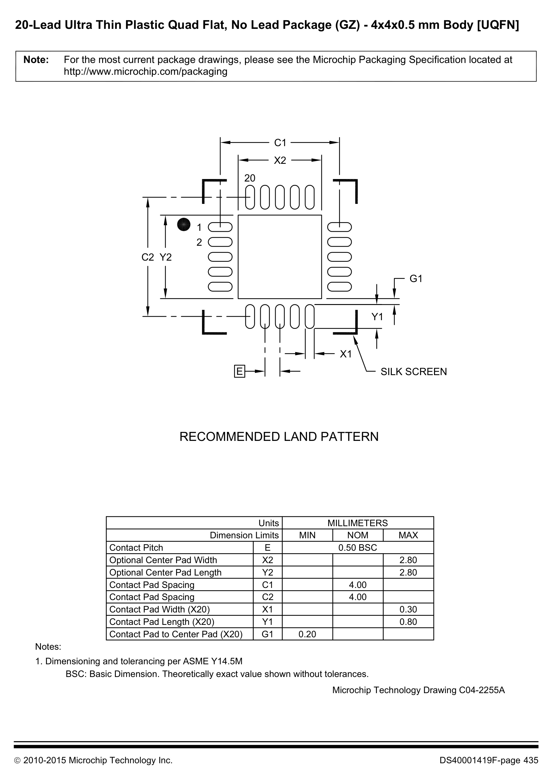
5. Recommended Land PatternLAND PATTERN
PIC16F1828T-I/SS (SSOP-20-208mil) - 5. Recommended Land Pattern
IPC-7351B Footprint (20 Pads)Expand ›
6. Application SchematicSCHEMATIC
PIC16F1828T-I/SS (SSOP-20-208mil) - 6. Application Schematic
Typical Application SchematicExpand ›
Original Datasheet Pinouts & Technical Drawings (16 figures · Page 1/2)
Showing 1–12 of 16 uncropped original figures for PIC16F1828T
P1 · p01_fig01377×200px
PIC16F1828T-I/SS (SSOP-20-208mil) — 14/20-Pin Flash Microcontrollers with XLP Technology
14/20-Pin Flash Microcontrollers with XLP Technology
P203 · p203_fig011753×672px
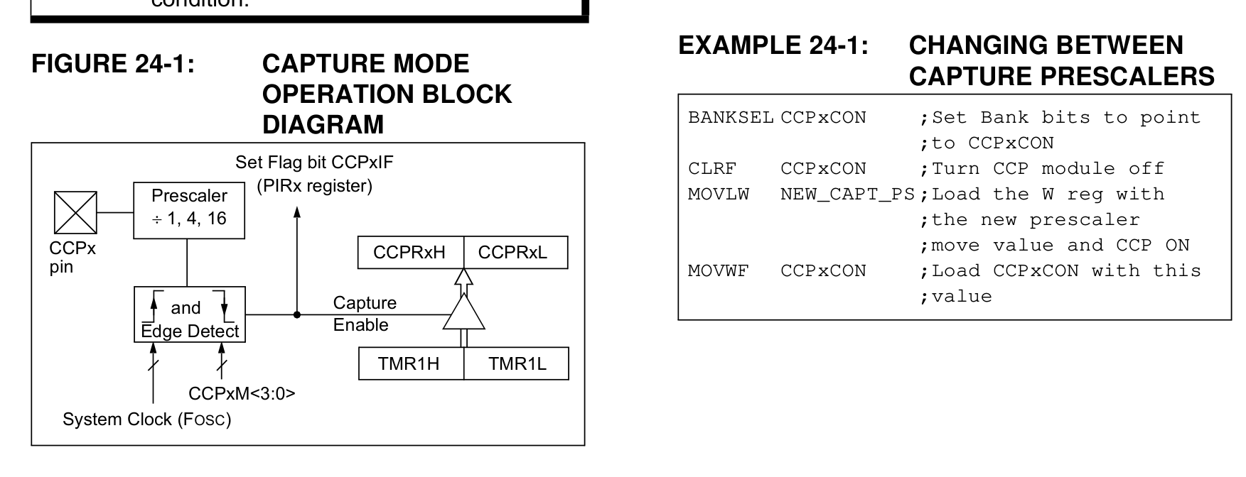
PIC16F1828T-I/SS (SSOP-20-208mil) — FIGURE 24-1: CAPTURE MODE OPERATION BLOCK DIAGRAM
FIGURE 24-1: CAPTURE MODE OPERATION BLOCK DIAGRAM
P205 · p205_fig011716×795px
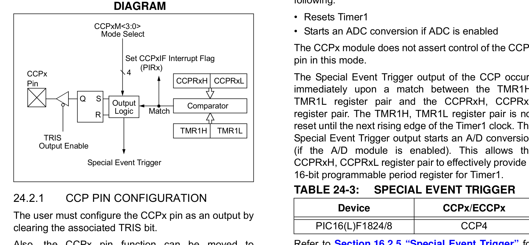
PIC16F1828T-I/SS (SSOP-20-208mil) — FIGURE 24-2: COMPARE MODE OPERATION BLOCK DIAGRAM
FIGURE 24-2: COMPARE MODE OPERATION BLOCK DIAGRAM
P205 · p205_fig021784×641px
PIC16F1828T-I/SS (SSOP-20-208mil) — The user must configure the CCPx pin as an output by clearing the associated TRIS bit.
The user must configure the CCPx pin as an output by clearing the associated TRIS bit.
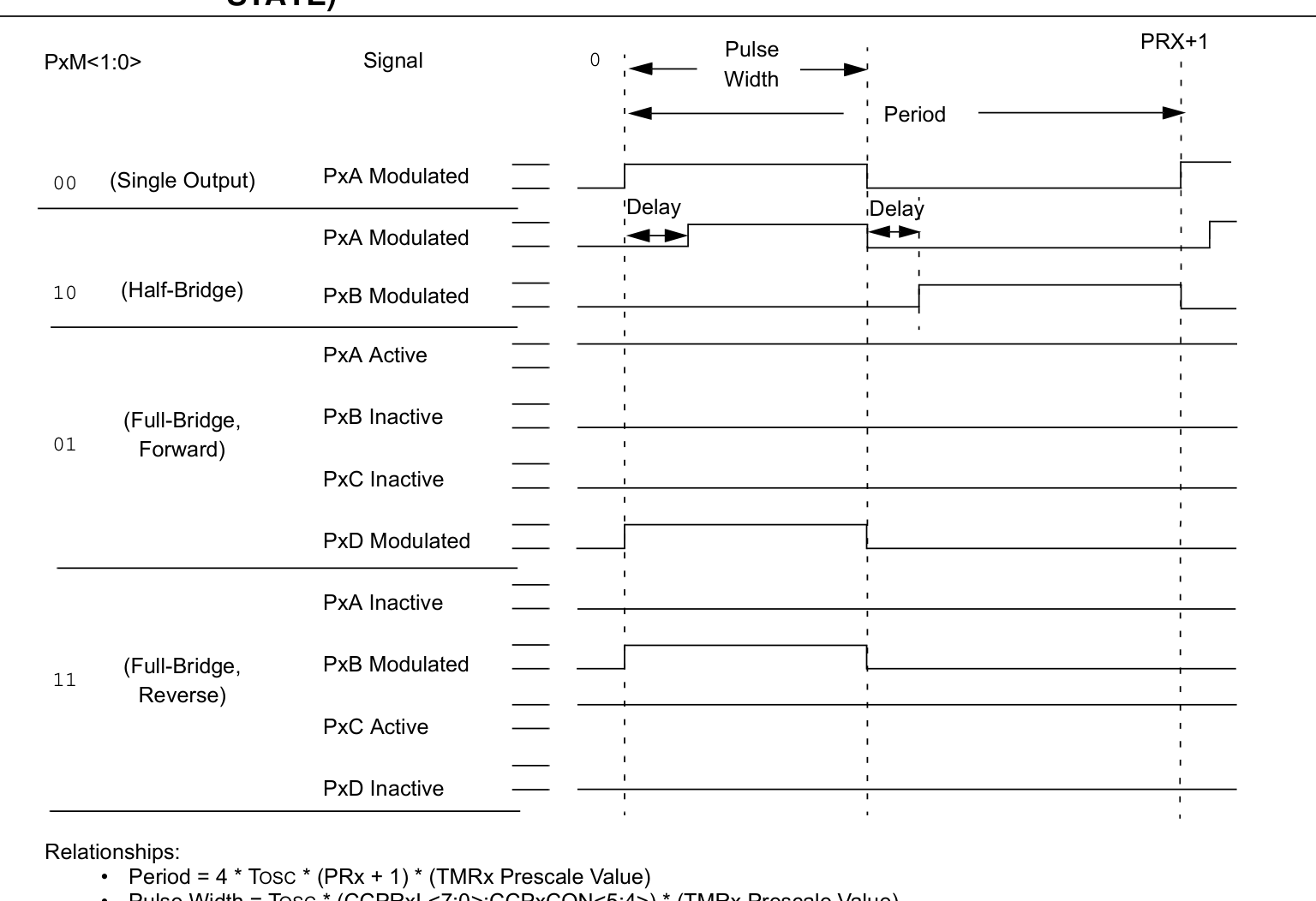
P212 · p212_fig011536×1052px
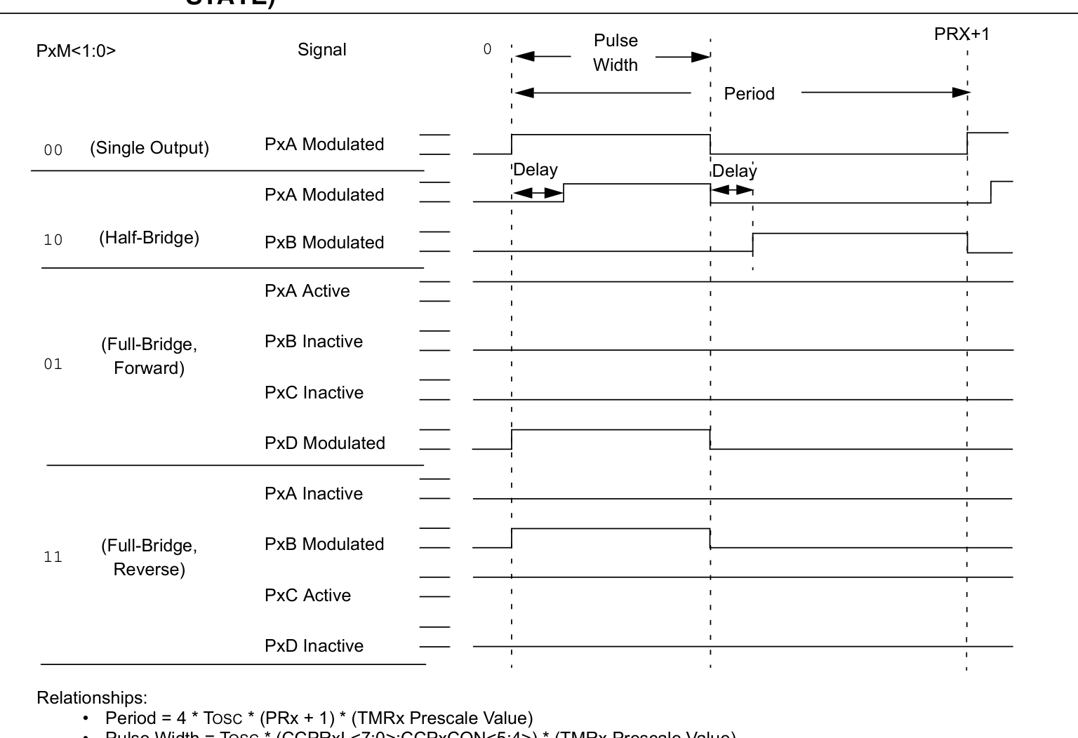
PIC16F1828T-I/SS (SSOP-20-208mil) — FIGURE 24-6: EXAMPLE PWM (ENHANCED MODE) OUTPUT RELATIONSHIPS (ACTIVE-HIGH STATE)
FIGURE 24-6: EXAMPLE PWM (ENHANCED MODE) OUTPUT RELATIONSHIPS (ACTIVE-HIGH STATE)
P212 · p212_fig01P212
PIC16F1828T-I/SS (SSOP-20-208mil) — Datasheet Page 212 (p212_fig01)
Datasheet Page 212 (p212_fig01)
P223 · p223_fig011738×565px
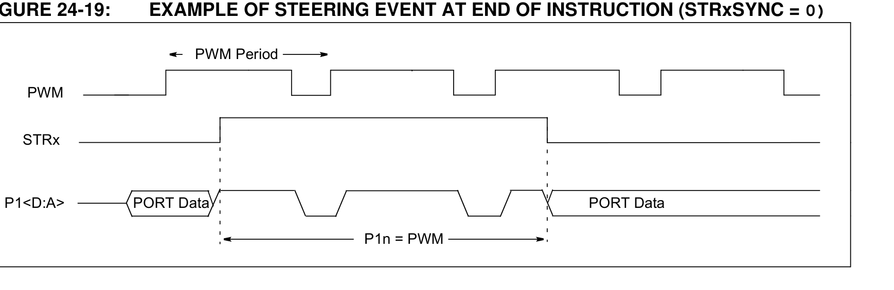
PIC16F1828T-I/SS (SSOP-20-208mil) — FIGURE 24-19: EXAMPLE OF STEERING EVENT AT END OF INSTRUCTION (STRxSYNC = 0)
FIGURE 24-19: EXAMPLE OF STEERING EVENT AT END OF INSTRUCTION (STRxSYNC = 0)
P223 · p223_fig021777×682px
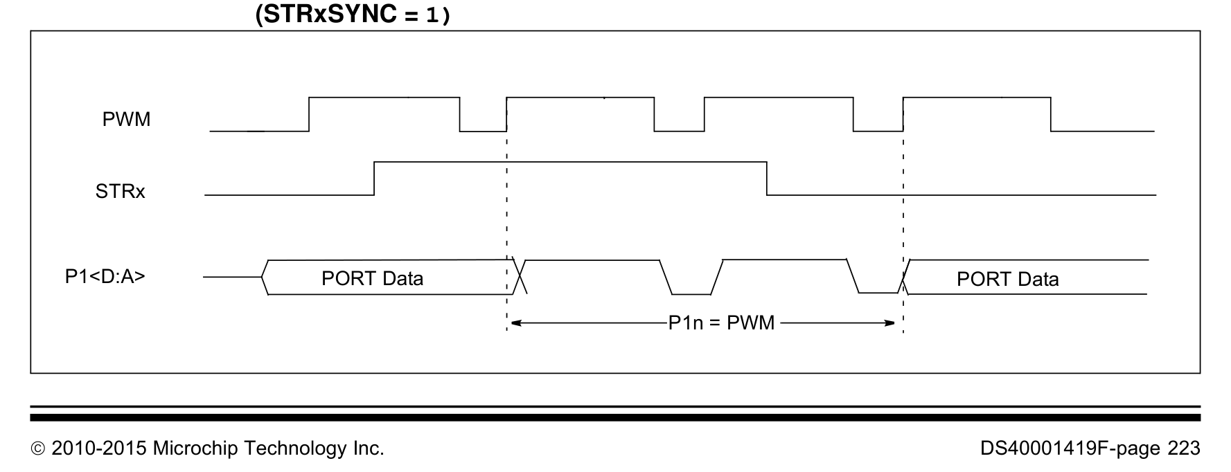
PIC16F1828T-I/SS (SSOP-20-208mil) — FIGURE 24-20: EXAMPLE OF STEERING EVENT AT BEGINNING OF INSTRUCTION (STRxSYNC = 1)
FIGURE 24-20: EXAMPLE OF STEERING EVENT AT BEGINNING OF INSTRUCTION (STRxSYNC = 1)
P323 · p323_fig011416×1013px
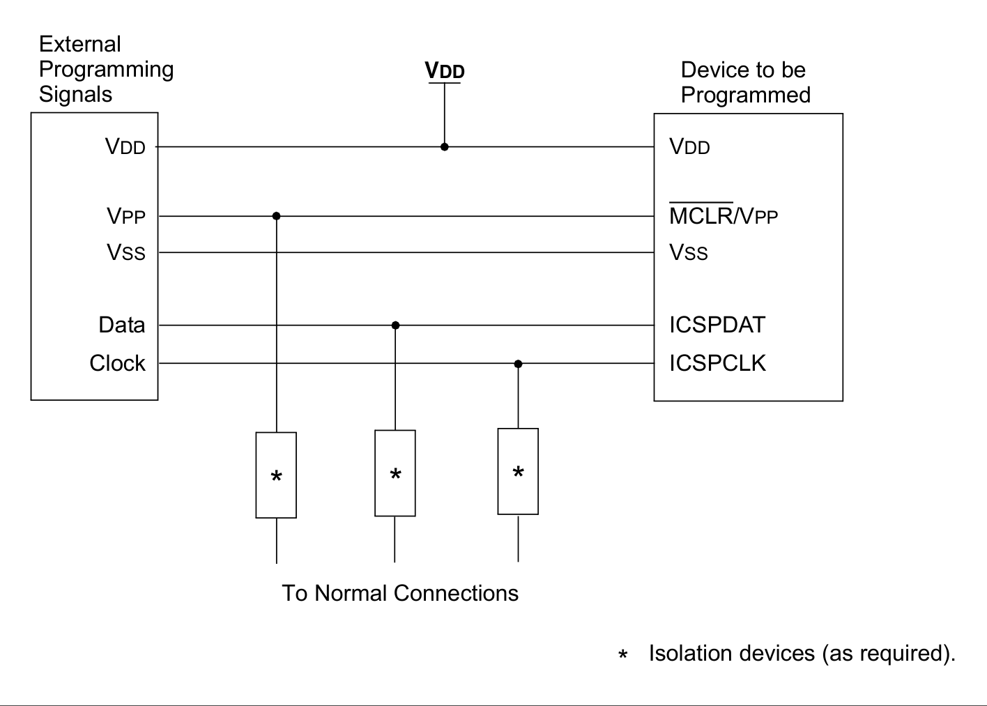
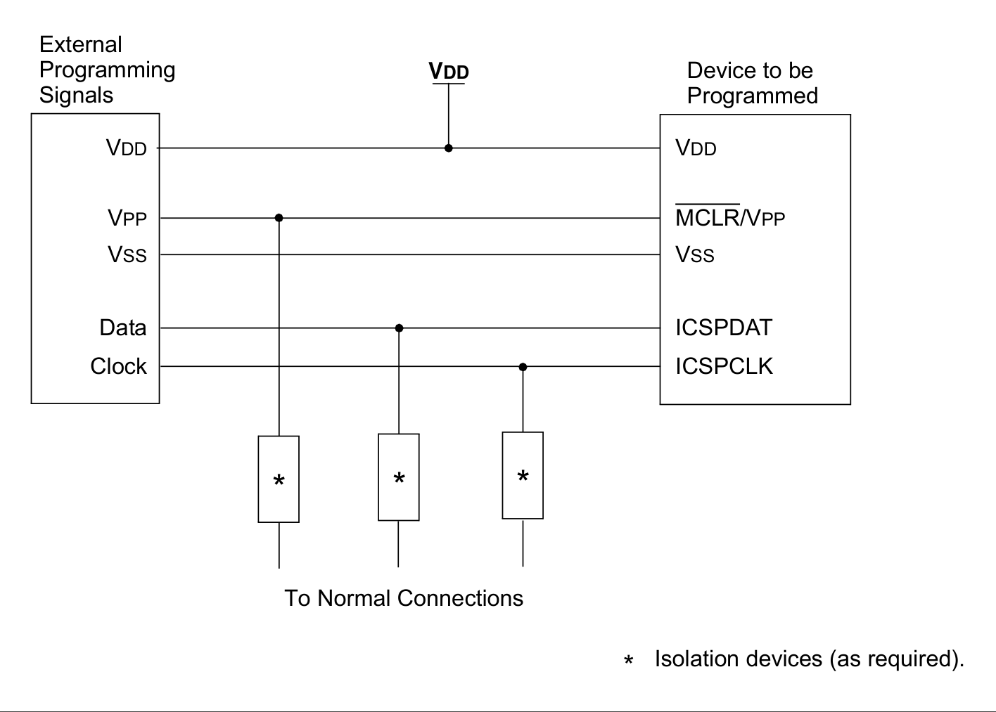
PIC16F1828T-I/SS (SSOP-20-208mil) — FIGURE 28-4: TYPICAL CONNECTION FOR ICSP™ PROGRAMMING
FIGURE 28-4: TYPICAL CONNECTION FOR ICSP™ PROGRAMMING
P323 · p323_fig01P323
PIC16F1828T-I/SS (SSOP-20-208mil) — Datasheet Page 323 (p323_fig01)
Datasheet Page 323 (p323_fig01)
P410 · p410_fig011756×2423px
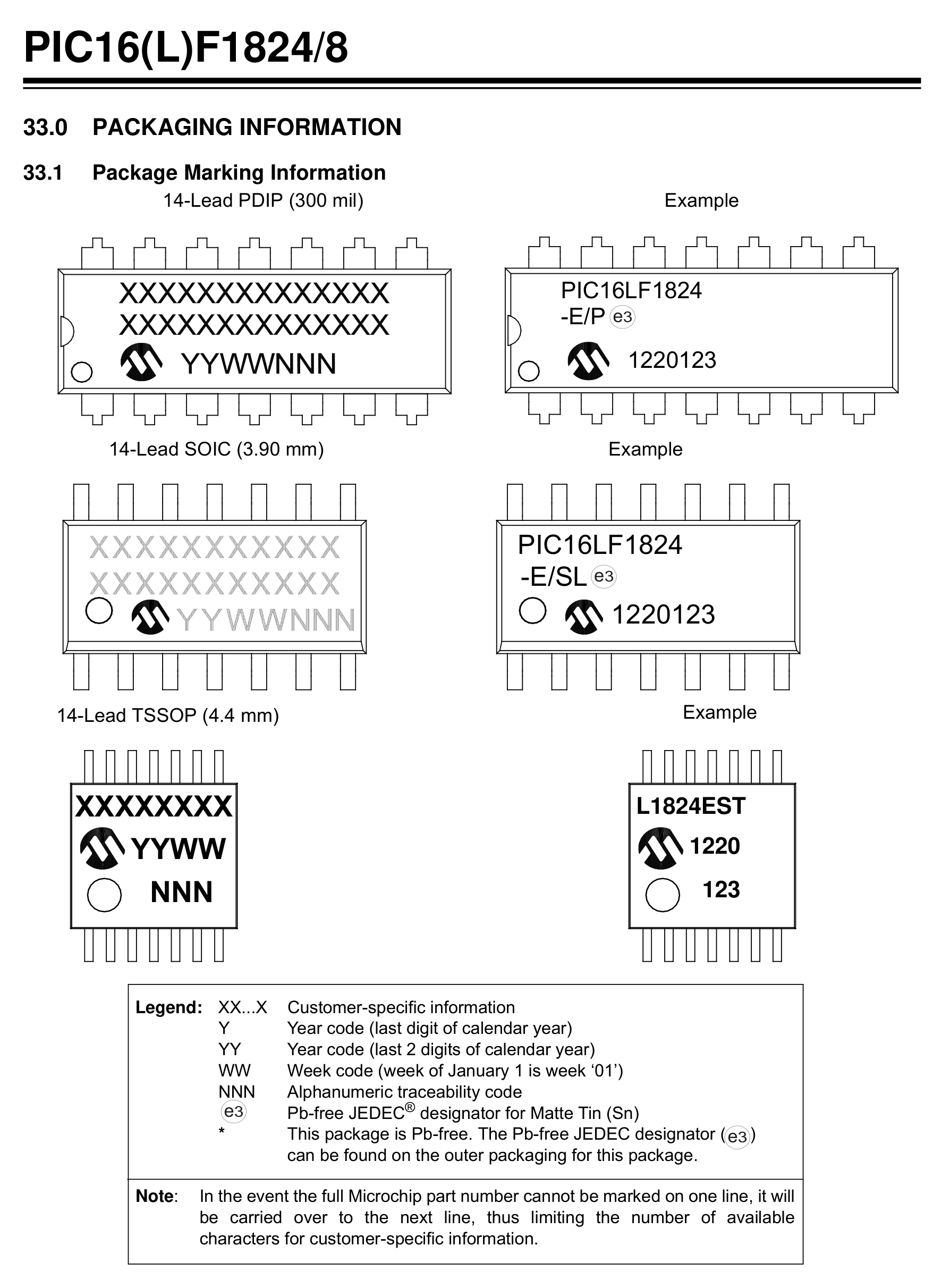
PIC16F1828T-I/SS (SSOP-20-208mil) — DS40001419F-page 410  2010-2015 Microchip Technology Inc.
DS40001419F-page 410  2010-2015 Microchip Technology Inc.
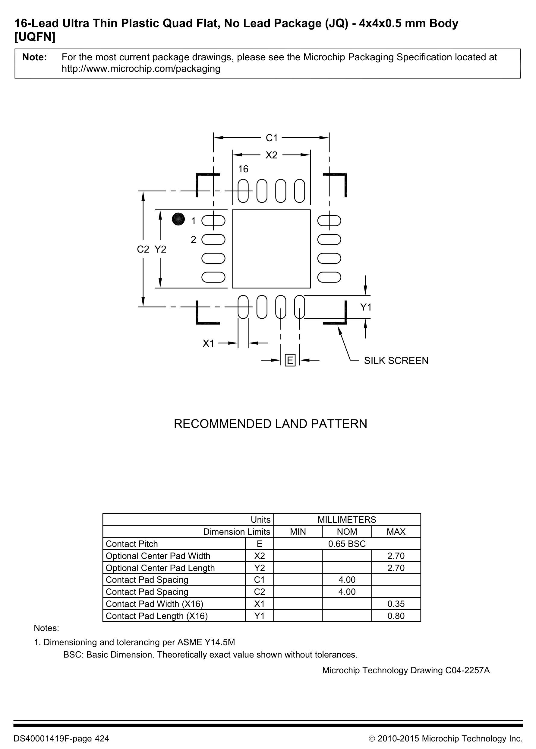
P424 · p424_fig011778×2482px
PIC16F1828T-I/SS (SSOP-20-208mil) — DS40001419F-page 424  2010-2015 Microchip Technology Inc. | RECOMMENDED LAND PATTERN | For the most current package drawings, please see the Microchip Packaging Specification located at http://www.microchip.com/packaging Note: | SILK SCREE
DS40001419F-page 424  2010-2015 Microchip Technology Inc. | RECOMMENDED LAND PATTERN | For the most current package drawings, please see the Microchip Packaging Specification located at http://www.microchip.com/packaging Note: | SILK SCREE
Page 1 / 2 (16 extracted figures)

Technical Specifications & Part Details (PIC16F1828T-I/SS)

Summary of electrical parameters, mechanical dimensions, voltage range and peripheral interfaces from Datasheet (EN)
Standard Electronic & Interconnect Component
Detailed Overview:PIC16F1828T-I/SS (SSOP-20-208mil) is a 20-pin standard electronic & interconnect component featuring a 7.20 × 5.30 × 1.85 mm mechanical envelope (lead pitch e = 0.65 mm). Rated for 1.8V-5.5V supply operation across -40°C ~ +85°C (Industrial Grade) with integrated SPI, I2C, ADC, DAC, PWM interfaces.
Operating Supply VoltageV_CC / V_DD
1.8V-5.5V
Place 100nF + 10µF X7R decoupling capacitors < 2mm from supply pins
Ambient Operating TemperatureT_A
-40°C ~ +85°C (Industrial Grade)
Industrial temperature grade; T_J(max) = +125°C
Clock / RF Operating Frequencyf_CLK / f_RF
32 MHz
Extracted from authoritative PDF specification tables
Current & Power RatingI_OUT / I_CC
I_GPIO(max) = ±20 mA / pin | I_VDD(total) ≤ 150 mA
Observe per-pin absolute maximum current limits
Package Envelope (D × E × A)D × E × A
7.20 × 5.30 × 1.85 mm (A1=0.15 mm)
Package family: TSSOP (SSOP-20-208mil)
Pin Count & Lead PitchN / e
20 Pins | Pitch e = 0.65 mm (25.6 mil)
Normalized to Center-to-Center Span C per IPC-7351B
Integrated Peripheral InterfacesBuses
SPI, I2C, ADC, DAC, PWM
Cross-linked with 4D Pinout & Schematic Symbol
Reflow & Moisture SensitivityIPC / MSL
IPC-7351B Level B | J-STD-020 (Peak 260°C) | MSL-3
60% windowed solder paste stencil on thermal EPAD
Engineering Safety Alert: Verify Pin-1 chamfer orientation on Top Silkscreen prior to SMT pick-and-place assembly.
Engineering Safety Alert: Connect exposed thermal pad (if present) to internal ground plane via 0.3mm stitched thermal vias.

5-Point Standards Verification

Automated compliance checks prior to export
5/5 PASS
IEEE-315 Symbol20 auto-grouped pins
OK
IPC-7351B Land Pattern20 pads · Pitch 0.65mm
OK
IPC-7525 60% Solder PasteReflow 1:1 Standard
OK
DFM Rules JLCPCB / PCBWayMin pad clearance: 0.25mm
OK
3D STEP AP214 & GLBAligned coordinate origin (0,0,0)
OK

Hardware Verification & Community Engineering Reviews

Summary of electrical parameters, mechanical dimensions, voltage range and peripheral interfaces from Datasheet
5.00 PCB Verified

Mechanical Dimensions & Land Pattern (SSOP-20-208mil)

Extracted from Datasheet & IPC-7351B Normalized
mm
Package Body (D × E)Nominal
7.20 × 5.30 mm
Height (A) & Pitch (e)IPC-7351B
A=1.85mm · e=0.65mm
Pad Size (W × L)Level B
0.42 × 1.60 mm
Pins / Total PadsTopology
20P / 20Pad (DUAL_ROW)

Recommended Companion BOM & Drop-In Equivalents

Passive external components per reference schematic and 1:1 pin-compatible alternatives
DFM READY
Designator / Replacement MPNValue / PackageFunction & PCB Layout Rule
N/A
BOM
Per application circuit
SSOP-20-208mil
Size power & signal trace widths for rated load current following IPC-2221 clearance rules.

Technical Frequently Asked Questions (FAQ) — PIC16F1828T-I/SS (SSOP-20-208mil)

Quick answers covering Pinout, IPC-7351B Land Pattern dimensions, and CAD export formats
IPC-7351B / IEEE-315

What is the Pinout and operating voltage specification of PIC16F1828T-I/SS (SSOP-20-208mil)?

Manufactured by MICROCHIP, the PIC16F1828T-I/SS is housed in a SSOP-20-208mil package with 20 pins and a 0.65 mm lead pitch, supporting a VCC supply range of 1.8V-5.5V. Key pins include: 1 (VDD: Power Supply Input (VDD — 1.8V-5.5V)), 2 (RA5: Multiplexed I/O & Peripheral Pin RA5 (General)), 3 (RA4: Multiplexed I/O & Peripheral Pin RA4 (General)), 4 (RA3/MCLR#/VPP: Multiplexed I/O & Peripheral Pin RA3/MCLR#/VPP (General)), 5 (RC5: Multiplexed I/O & Peripheral Pin RC5 (General)), 6 (RC4: Multiplexed I/O & Peripheral Pin RC4 (General)).

What are the IPC-7351B PCB Footprint dimensions for PIC16F1828T-I/SS?

Normalized from the official datasheet mechanical drawing per IPC-7351B (Density Level B Nominal), PIC16F1828T-I/SS (SSOP-20-208mil) has a nominal body envelope of 5.30 × 7.20 mm, pitch e = 0.65 mm, and 20 copper pads.

Where can I download KiCad (.kicad_mod, .kicad_sym), Fusion 360 (.lbr), and 3D STEP models for PIC16F1828T-I/SS?

You can download the verified open-hardware (CERN-OHL-P-2.0) CAD library bundle for PIC16F1828T-I/SS (MICROCHIP, SSOP-20-208mil) directly on this page, including KiCad 8 Footprints (.kicad_mod), Schematic Symbols (.kicad_sym), Autodesk Fusion 360 / Eagle (.lbr), and 3D STEP AP214 / WebGL GLB models.

Static Reference Appendix: Pinout Table (20 pins) & PIC16F1828T Family VariantsExpand static table
Pin #Signal NameElectrical TypeFunctional Description & Design Notes
1VDDPower_InPrimary positive power supply input (VDD) operating in the 1.8V-5.5V domain (Max rating: 5.5V).
2RA5Digital_IOSignal terminal RA5 (I/O, 1.8V-5.5V domain). Multiplexed alternate functions: RA5. Supported peripheral buses: General.
3RA4Digital_IOSignal terminal RA4 (I/O, 1.8V-5.5V domain). Multiplexed alternate functions: RA4. Supported peripheral buses: General.
4RA3/MCLR#/VPPDigital_IOSignal terminal RA3/MCLR#/VPP (I/O, 1.8V-5.5V domain). Multiplexed alternate functions: RA3/MCLR#/VPP. Supported peripheral buses: General.
5RC5Digital_IOSignal terminal RC5 (I/O, 1.8V-5.5V domain). Multiplexed alternate functions: RC5. Supported peripheral buses: General.
6RC4Digital_IOSignal terminal RC4 (I/O, 1.8V-5.5V domain). Multiplexed alternate functions: RC4. Supported peripheral buses: General.
7RC3Digital_IOSignal terminal RC3 (I/O, 1.8V-5.5V domain). Multiplexed alternate functions: RC3. Supported peripheral buses: General.
8RC6Digital_IOSignal terminal RC6 (I/O, 1.8V-5.5V domain). Multiplexed alternate functions: RC6. Supported peripheral buses: General.
9RC7Digital_IOSignal terminal RC7 (I/O, 1.8V-5.5V domain). Multiplexed alternate functions: RC7. Supported peripheral buses: General.
10RB7Digital_IOSignal terminal RB7 (I/O, 1.8V-5.5V domain). Multiplexed alternate functions: RB7. Supported peripheral buses: General.
11RB6Digital_IOSignal terminal RB6 (I/O, 1.8V-5.5V domain). Multiplexed alternate functions: RB6. Supported peripheral buses: General.
12RB5Digital_IOSignal terminal RB5 (I/O, 1.8V-5.5V domain). Multiplexed alternate functions: RB5. Supported peripheral buses: General.
13RB4Digital_IOSignal terminal RB4 (I/O, 1.8V-5.5V domain). Multiplexed alternate functions: RB4. Supported peripheral buses: General.
14RC2Digital_IOSignal terminal RC2 (I/O, 1.8V-5.5V domain). Multiplexed alternate functions: RC2. Supported peripheral buses: General.
15RC1Digital_IOSignal terminal RC1 (I/O, 1.8V-5.5V domain). Multiplexed alternate functions: RC1. Supported peripheral buses: General.
16RC0Digital_IOSignal terminal RC0 (I/O, 1.8V-5.5V domain). Multiplexed alternate functions: RC0. Supported peripheral buses: General.
17RA2Digital_IOSignal terminal RA2 (I/O, 1.8V-5.5V domain). Multiplexed alternate functions: RA2. Supported peripheral buses: General.
18RA1/ICSPCLKDigital_IOSignal terminal RA1/ICSPCLK (I/O, 1.8V-5.5V domain). Multiplexed alternate functions: RA1/ICSPCLK. Supported peripheral buses: General.
19RA0/ICSPDATDigital_IOSignal terminal RA0/ICSPDAT (I/O, 1.8V-5.5V domain). Multiplexed alternate functions: RA0/ICSPDAT. Supported peripheral buses: General.
20VSSGND0V electrical ground return terminal (VSS) for internal core logic, I/O drivers, and analog sub-blocks.