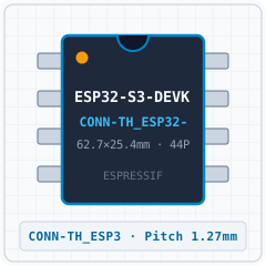
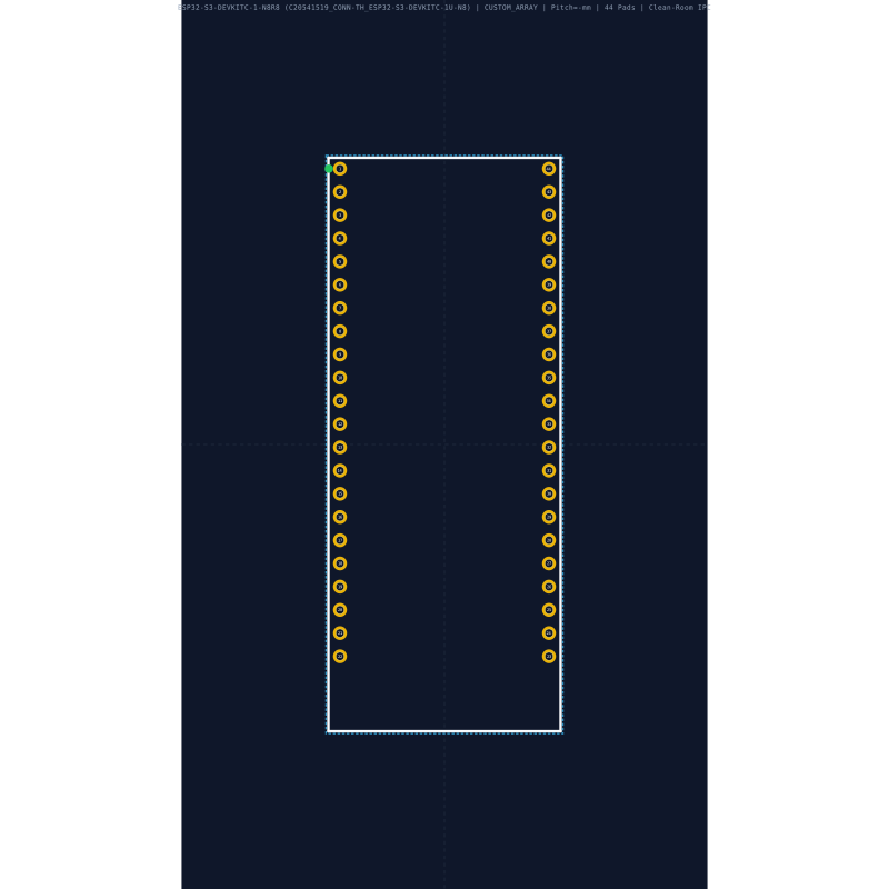
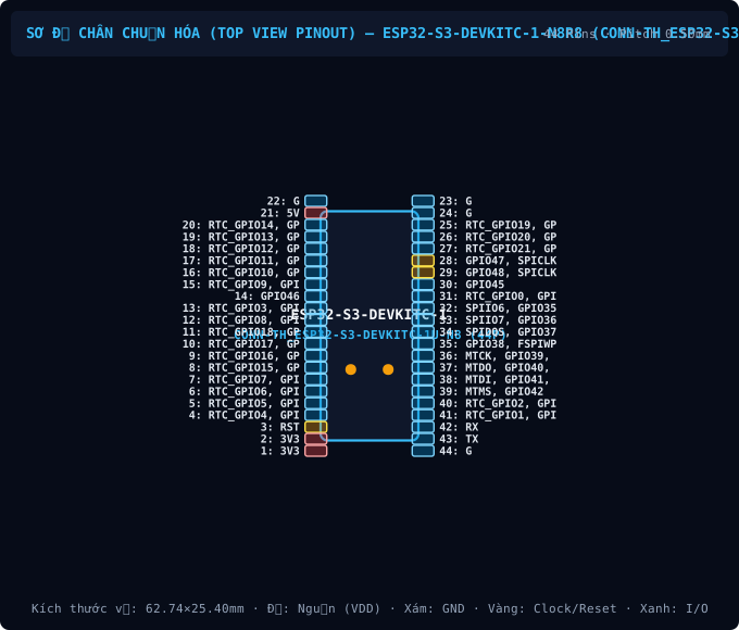
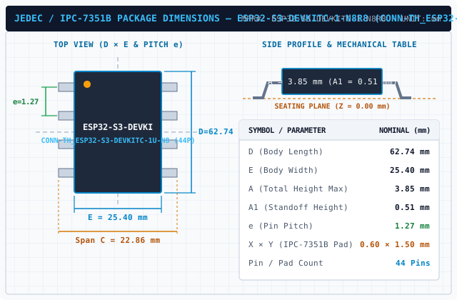
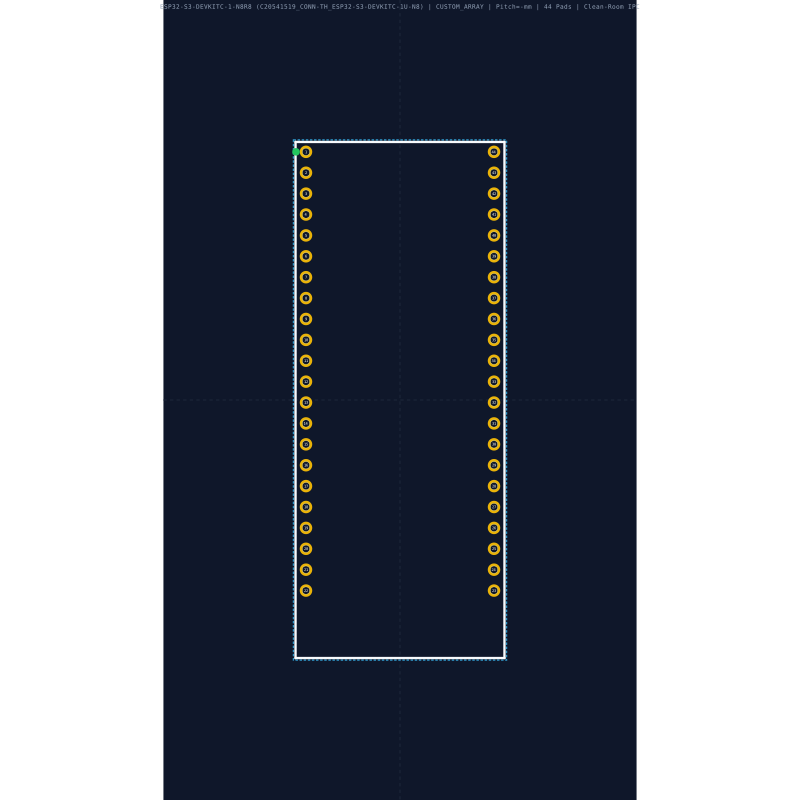
Mechanical Dimensions & Land Pattern (CONN-TH_ESP32-S3-DEVKITC-1U-N8)
Extracted from Datasheet & IPC-7351B NormalizedRecommended Companion BOM & Drop-In Equivalents
Passive external components per reference schematic and 1:1 pin-compatible alternatives| Designator / Replacement MPN | Value / Package | Function & PCB Layout Rule |
|---|---|---|
| C1, C2 BOM | 22µF (or 10µF) X5R + 100nF X7R 0805 + 0402 | 3V3 supply decoupling for ~500mA Wi-Fi TX bursts — place closest to 3V3 pin; supply must deliver >= 600mA. |
| R_en + C_en BOM | R = 10kΩ to 3V3 + C = 1µF to GND 0402 / 0603 | Power-On Reset RC delay at EN (CHIP_PU) — 1µF capacitor at EN is REQUIRED for reliable cold boot. |
| R_boot + SW1 BOM | 10kΩ Pull-up + BOOT button 0402 + SMD | Firmware boot-mode strap (IO0 on ESP32/S2/S3, IO9 on ESP32-C3) — on C3 pull IO8 high via 10kΩ for UART/USB download. |
| D_esd BOM | USBLC6-2SC6 / LESD5D5.0CT1G SOT-23-6 / SOD-523 | ESD surge protection on USB D+/D- — place right next to USB Type-C connector before IO18/IO19/IO20. |
| ESP32-S3-MINI-1-N8 / 1U-N4R2 Espressif | 100% Drop-in | Same 15.4×15.4mm 65-pad footprint as ESP32-S2-MINI-2 — verify USB GPIO 19/20 pin mapping. |
Technical Frequently Asked Questions (FAQ) — ESP32-S3-DEVKITC-1-N8R8 (CONN-TH_ESP32-S3-DEVKITC-1U-N8)
Quick answers covering Pinout, IPC-7351B Land Pattern dimensions, and CAD export formatsWhat is the Pinout and operating voltage specification of ESP32-S3-DEVKITC-1-N8R8 (CONN-TH_ESP32-S3-DEVKITC-1U-N8)?
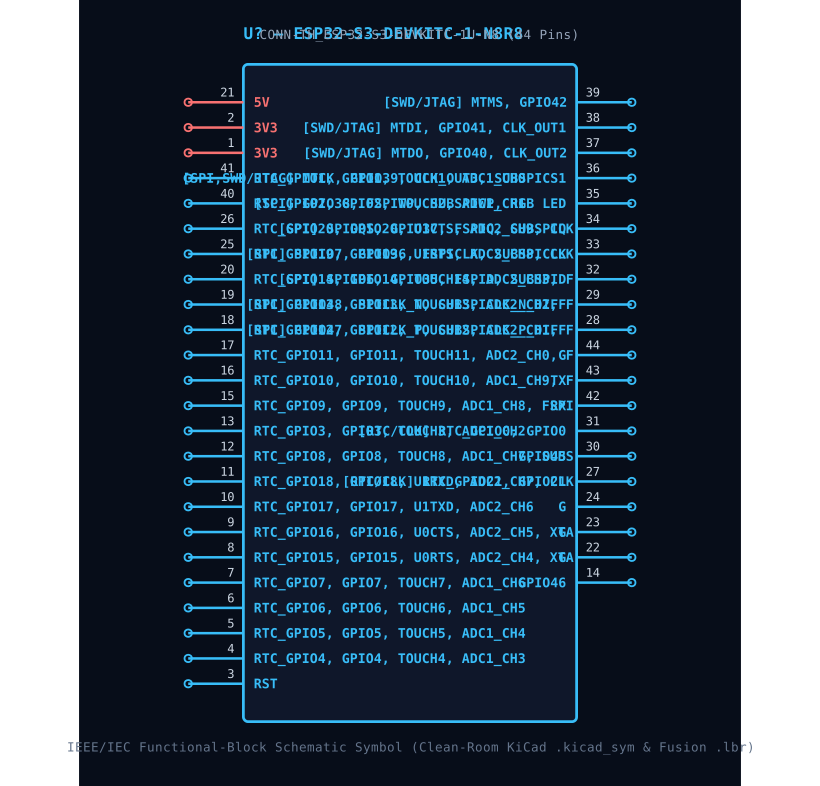
Manufactured by ESPRESSIF, the ESP32-S3-DEVKITC-1-N8R8 is housed in a CONN-TH_ESP32-S3-DEVKITC-1U-N8 package with 44 pins and a 0.50 mm lead pitch. Key pins include: 1 (3V3: Power Supply Input (3V3 — 3.3V VDD3P3 (3.0V ~ 3.6V))), 2 (3V3: Power Supply Input (3V3 — 3.3V VDD3P3 (3.0V ~ 3.6V))), 3 (RST: Multiplexed I/O & Peripheral Pin RST (General)), 4 (NC: No Connect (Leave Floating)), 5 (IO2: GPIO2 / RTC_GPIO2 / TOUCH2 / ADC1_CH1), 6 (IO3: GPIO3 / RTC_GPIO3 / TOUCH3 / ADC1_CH2 (JTAG Source Strap)).
What are the IPC-7351B PCB Footprint dimensions for ESP32-S3-DEVKITC-1-N8R8?
Normalized from the official datasheet mechanical drawing per IPC-7351B (Density Level B Nominal), ESP32-S3-DEVKITC-1-N8R8 (CONN-TH_ESP32-S3-DEVKITC-1U-N8) has a nominal body envelope of 25.40 × 62.74 mm, pitch e = 0.50 mm, and 44 copper pads.
Where can I download KiCad (.kicad_mod, .kicad_sym), Fusion 360 (.lbr), and 3D STEP models for ESP32-S3-DEVKITC-1-N8R8?
You can download the verified open-hardware (CERN-OHL-P-2.0) CAD library bundle for ESP32-S3-DEVKITC-1-N8R8 (ESPRESSIF, CONN-TH_ESP32-S3-DEVKITC-1U-N8) directly on this page, including KiCad 8 Footprints (.kicad_mod), Schematic Symbols (.kicad_sym), Autodesk Fusion 360 / Eagle (.lbr), and 3D STEP AP214 / WebGL GLB models.
Static Reference Appendix: Pinout Table (44 pins) & ESP32-S3 Family VariantsExpand static table
| Pin # | Signal Name | Electrical Type | Functional Description & Design Notes |
|---|---|---|---|
| 1 | 3V3 | Power_In | Primary positive power supply input (3V3) operating in the 3.3V VDD3P3 (3.0V ~ 3.6V) domain (Max rating: 3.6V). |
| 2 | 3V3 | Power_In | Primary positive power supply input (3V3) operating in the 3.3V VDD3P3 (3.0V ~ 3.6V) domain (Max rating: 3.6V). |
| 3 | RST | Digital_IO | Signal terminal RST (I/O, 3.3V VDD3P3 (3.0V ~ 3.6V) domain). Multiplexed alternate functions: RST. Supported peripheral buses: General. |
| 4 | NC | No_Connect | No Connect (Leave Floating) |
| 5 | IO2 | Digital_IO | GPIO2 / RTC_GPIO2 / TOUCH2 / ADC1_CH1 |
| 6 | IO3 | Digital_IO | GPIO3 / RTC_GPIO3 / TOUCH3 / ADC1_CH2 (JTAG Source Strap) |
| 7 | NC | No_Connect | No Connect (Leave Floating) |
| 8 | IO0 | Digital_IO | GPIO0 / RTC_GPIO0 (Chip Boot Mode Strapping Pin) |
| 9 | IO4 | Digital_IO | GPIO4 / RTC_GPIO4 / TOUCH4 / ADC1_CH3 |
| 10 | IO5 | Digital_IO | GPIO5 / RTC_GPIO5 / TOUCH5 / ADC1_CH4 |
| 11 | IO6 | Digital_IO | GPIO6 / RTC_GPIO6 / TOUCH6 / ADC1_CH5 |
| 12 | IO7 | Digital_IO | GPIO7 / RTC_GPIO7 / TOUCH7 / ADC1_CH6 |
| 13 | IO15 | Digital_IO | GPIO15 / RTC_GPIO15 / U0RTS / ADC2_CH4 / XTAL_32K_P |
| 14 | GPIO46 | Digital_IO | Signal terminal GPIO46 (I/O, 3.3V VDD3P3 (3.0V ~ 3.6V) domain). Multiplexed alternate functions: GPIO46. Supported peripheral buses: General. |
| 15 | IO17 | Digital_IO | GPIO17 / RTC_GPIO17 / U1TXD / ADC2_CH6 |
| 16 | IO18 | Digital_IO | GPIO18 / RTC_GPIO18 / U1RXD / ADC2_CH7 / CLK_OUT3 |
| 17 | IO8 | Digital_IO | GPIO8 / RTC_GPIO8 / TOUCH8 / ADC1_CH7 / SUBSPICS1 |
| 18 | IO19 | Digital_IO | GPIO19 / RTC_GPIO19 / USB_D- / U1RTS / ADC2_CH8 |
| 19 | IO20 | Digital_IO | GPIO20 / RTC_GPIO20 / USB_D+ / U1CTS / ADC2_CH9 |
| 20 | IO9 | Digital_IO | GPIO9 / RTC_GPIO9 / TOUCH9 / ADC1_CH8 / FSPIHD |
| 21 | 5V | Power_In | Primary positive power supply input (5V) operating in the 3.3V VDD3P3 (3.0V ~ 3.6V) domain (Max rating: 3.6V). |
| 22 | G | Digital_IO | Signal terminal G (I/O, 3.3V VDD3P3 (3.0V ~ 3.6V) domain). Multiplexed alternate functions: G. Supported peripheral buses: General. |
| 23 | G | Digital_IO | Signal terminal G (I/O, 3.3V VDD3P3 (3.0V ~ 3.6V) domain). Multiplexed alternate functions: G. Supported peripheral buses: General. |
| 24 | G | Digital_IO | Signal terminal G (I/O, 3.3V VDD3P3 (3.0V ~ 3.6V) domain). Multiplexed alternate functions: G. Supported peripheral buses: General. |
| 25 | IO14 | Digital_IO | GPIO14 / RTC_GPIO14 / TOUCH14 / ADC2_CH3 / FSPIWP |
| 26 | IO21 | Digital_IO | GPIO21 / RTC_GPIO21 |
| 27 | RTC_GPIO21, GPIO21 | Digital_IO | Signal terminal RTC_GPIO21, GPIO21 (I/O, 3.3V VDD3P3 (3.0V ~ 3.6V) domain). Multiplexed alternate functions: RTC_GPIO21, GPIO21. Supported peripheral buses: RTC/CLK. |
| 28 | IO33 | Digital_IO | GPIO33 / FSPIHD / SUBSPIHD / SPIIO4 |
| 29 | IO29 | Digital_IO | General Purpose Digital I/O Pin IO29 |
| 30 | GPIO45 | Digital_IO | Signal terminal GPIO45 (I/O, 3.3V VDD3P3 (3.0V ~ 3.6V) domain). Multiplexed alternate functions: GPIO45. Supported peripheral buses: General. |
| 31 | RTC_GPIO0, GPIO0 | Digital_IO | Signal terminal RTC_GPIO0, GPIO0 (I/O, 3.3V VDD3P3 (3.0V ~ 3.6V) domain). Multiplexed alternate functions: RTC_GPIO0, GPIO0. Supported peripheral buses: RTC/CLK. |
| 32 | IO32 | Digital_IO | General Purpose Digital I/O Pin IO32 |
| 33 | IO33 | Digital_IO | General Purpose Digital I/O Pin IO33 |
| 34 | IO34 | Digital_IO | General Purpose Digital I/O Pin IO34 |
| 35 | IO35 | Digital_IO | General Purpose Digital I/O Pin IO35 |
| 36 | IO36 | Digital_IO | General Purpose Digital I/O Pin IO36 |
| 37 | MTDO, GPIO40, CLK_OUT2 | Digital_IO | Signal terminal MTDO, GPIO40, CLK_OUT2 (I/O, 3.3V VDD3P3 (3.0V ~ 3.6V) domain). Multiplexed alternate functions: MTDO, GPIO40, CLK_OUT2. Supported peripheral buses: SWD/JTAG. |
| 38 | MTDI, GPIO41, CLK_OUT1 | Digital_IO | Signal terminal MTDI, GPIO41, CLK_OUT1 (I/O, 3.3V VDD3P3 (3.0V ~ 3.6V) domain). Multiplexed alternate functions: MTDI, GPIO41, CLK_OUT1. Supported peripheral buses: SWD/JTAG. |
| 39 | MTMS, GPIO42 | Digital_IO | Signal terminal MTMS, GPIO42 (I/O, 3.3V VDD3P3 (3.0V ~ 3.6V) domain). Multiplexed alternate functions: MTMS, GPIO42. Supported peripheral buses: SWD/JTAG. |
| 40 | IO40 | Digital_IO | General Purpose Digital I/O Pin IO40 |
| 41 | IO41 | Digital_IO | General Purpose Digital I/O Pin IO41 |
| 42 | RX | Digital_IO | Signal terminal RX (I/O, 3.3V VDD3P3 (3.0V ~ 3.6V) domain). Multiplexed alternate functions: RX. Supported peripheral buses: General. |
| 43 | TX | Digital_IO | Signal terminal TX (I/O, 3.3V VDD3P3 (3.0V ~ 3.6V) domain). Multiplexed alternate functions: TX. Supported peripheral buses: General. |
| 44 | G | Digital_IO | Signal terminal G (I/O, 3.3V VDD3P3 (3.0V ~ 3.6V) domain). Multiplexed alternate functions: G. Supported peripheral buses: General. |