SY88953LMI (MLF-16(3x3)) — Symbol, Footprint IPC-7351B & 3D STEP Model

SY88953LMI

MICROCHIPID: C19398603MLF-16(3x3) · 17 Pins · Pitch 0.50mmIPC-7351B Verified5.0 (0)
SYNCHRONIZED 4D CROSS-PROBE MODETouch or hover any pin to highlight concurrently across Symbol, Footprint and 3D
1. SYMBOL
U1 · SY88953LMI (MLF-16(3x3))1DIN2VCC3VCC4/DIN5VTHN6SD7/SD8GND9/DOUT17EP16VTHP15/EN14SDLVL13GND12DOUT11VCC10VCCGrid Pitch = 2.54mm (IEEE-315)-17.8-12.7-7.6-2.52.57.612.717.817.812.77.62.5-2.5-7.6-12.7-17.8mm
2. 2D FOOTPRINT
1716151413876512111094321E=3.00mm · Pitch e=0.50mmD=3.00mm-3-2-101233210-1-2-3mm
3. 3D CAD MODEL
Package Body: 3.00mm × 3.00mm · Pitch: 0.50mm · Ruler Step: 1.00mmSynced <100ms

Synchronized Pinout (Symbol / 2D / 3D) (17/17)

Touch or hover any pin to highlight concurrently across Symbol, Footprint and 3D
PinSymbolTypeFunction (EN)
1DINI/OMultiplexed I/O & Peripheral Pin DIN (General)
2VCCPowerPower Supply Input (VCC — 3.0V to 3.6V)
3VCCPowerPower Supply Input (VCC — 3.0V to 3.6V)
4/DINI/OMultiplexed I/O & Peripheral Pin /DIN (General)
5VTHNI/OMultiplexed I/O & Peripheral Pin VTHN (General)
6SDI/OMultiplexed I/O & Peripheral Pin SD (General)
7/SDI/OMultiplexed I/O & Peripheral Pin /SD (General)
8GNDGNDGround Reference Pin (GND)
9/DOUTI/OMultiplexed I/O & Peripheral Pin /DOUT (General)
10VCCPowerPower Supply Input (VCC — 3.0V to 3.6V)
11VCCPowerPower Supply Input (VCC — 3.0V to 3.6V)
12DOUTI/OMultiplexed I/O & Peripheral Pin DOUT (General)
13GNDGNDGround Reference Pin (GND)
14SDLVLI/OMultiplexed I/O & Peripheral Pin SDLVL (General)
15/ENI/OMultiplexed I/O & Peripheral Pin /EN (General)
16VTHPI/OMultiplexed I/O & Peripheral Pin VTHP (General)
17EPGNDExposed Thermal & Ground Pad (EP)
PIN 1 DIN
I/O
Multiplexed I/O & Peripheral Pin DIN (General)
Design note: True data input w/50Ω resistor to V CC.
IPC-7351B Solder Density & Span C/G/Z Tuner

Live Embedded Datasheet PDF & Technical Drawing Gallery (6 Standard Drawings + 7 Extracted Figures)

Read the original datasheet PDF directly or click any drawing to view fullscreen
Open PDF in New Window ↗Read Datasheet PDF (.pdf)
PDF VIEWEROfficial Datasheet Document: SY88953LMI (MICROCHIP · MLF-16(3x3))
Scroll, search text (Ctrl+F), or expand directly inside the embedded PDF reader below
1. Realistic 3D PackageREPRESENTATIVE
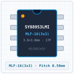
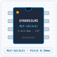
SY88953LMI (MLF-16(3x3)) - 1. Realistic 3D Package
Detailed solid 3D bodyExpand ›
2. Standard Pinout (Top View)CLEANROOM PINOUT
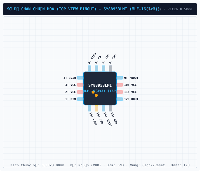
SY88953LMI (MLF-16(3x3)) - 2. Standard Pinout (Top View)
True package pinout (17 pins)Expand ›
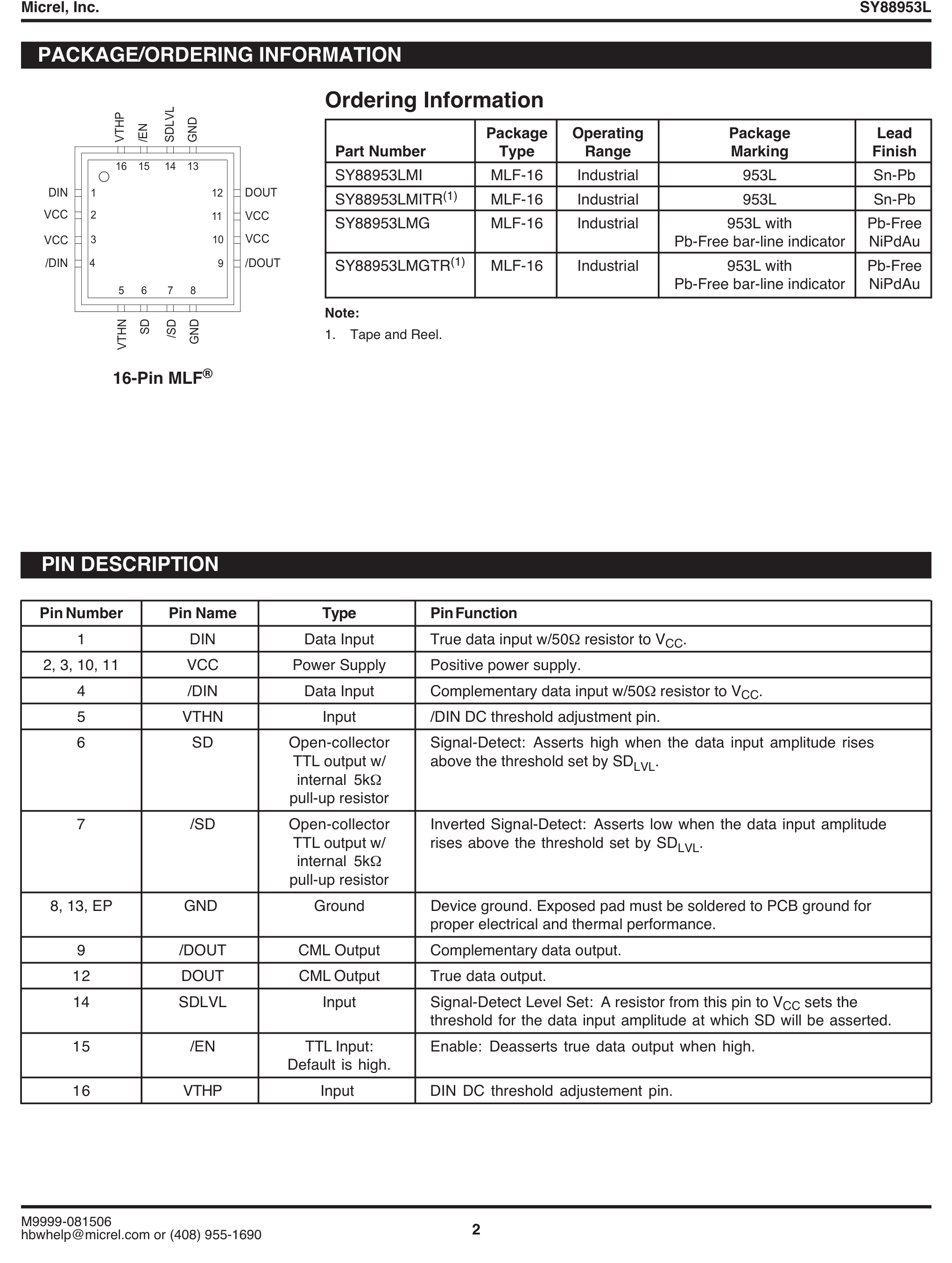
3. Original Datasheet PinoutPDF PINOUT
SY88953LMI (MLF-16(3x3)) - 3. Original Datasheet Pinout
Uncropped datasheet pin diagramExpand ›
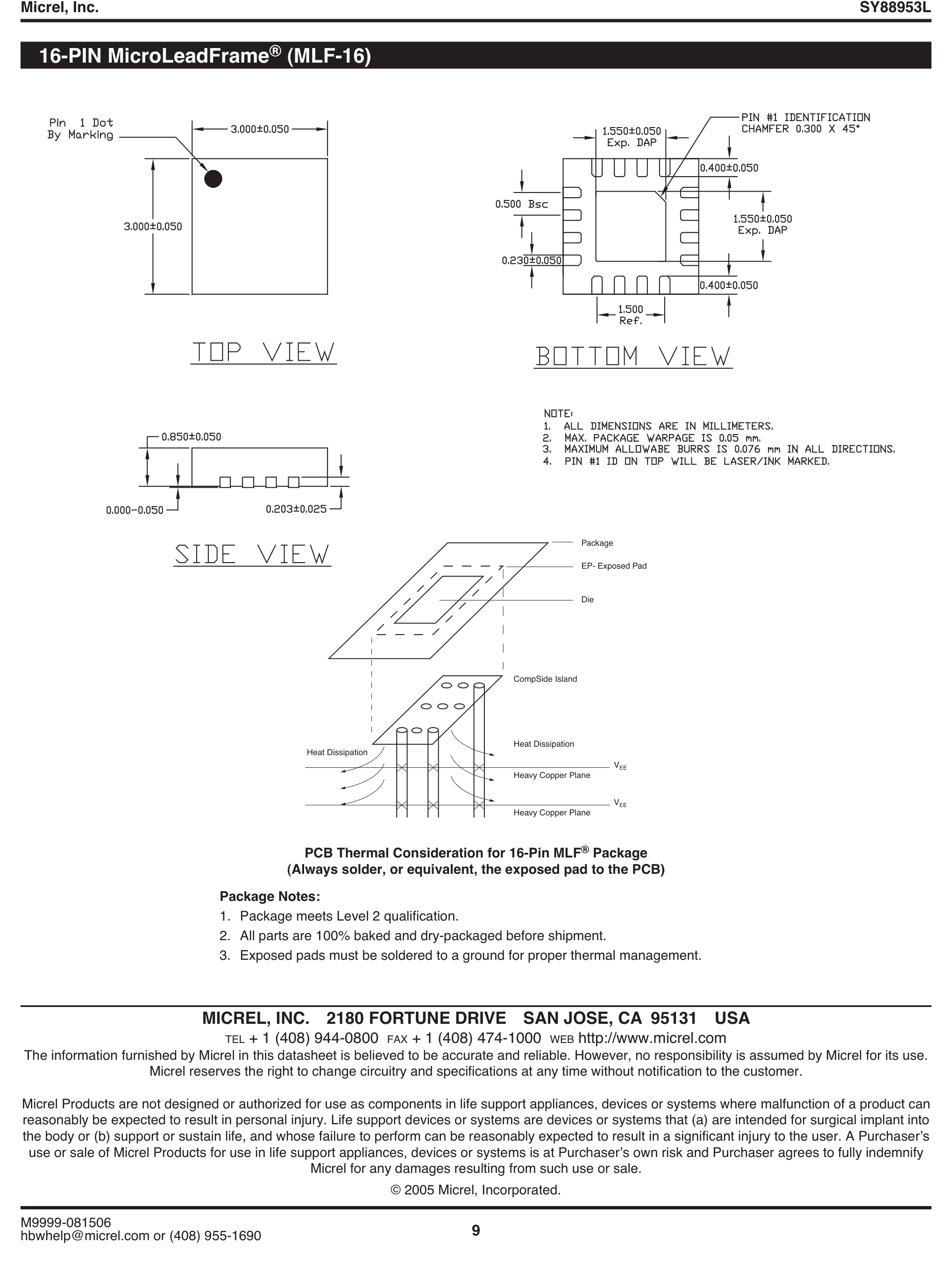
4. Package Dimensions (D×E×A)PACKAGE DIMENSIONS
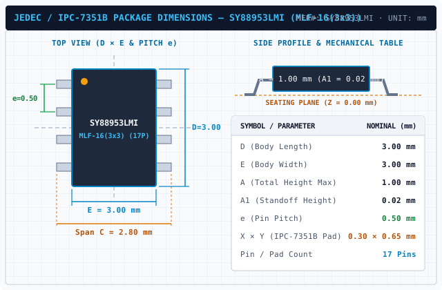
SY88953LMI (MLF-16(3x3)) - 4. Package Dimensions (D×E×A)
MLF-16(3x3) · 3.00×3.00mm · Pitch 0.50mmExpand ›
5. Recommended Land PatternLAND PATTERN
SY88953LMI (MLF-16(3x3)) - 5. Recommended Land Pattern
IPC-7351B Footprint (17 Pads)Expand ›
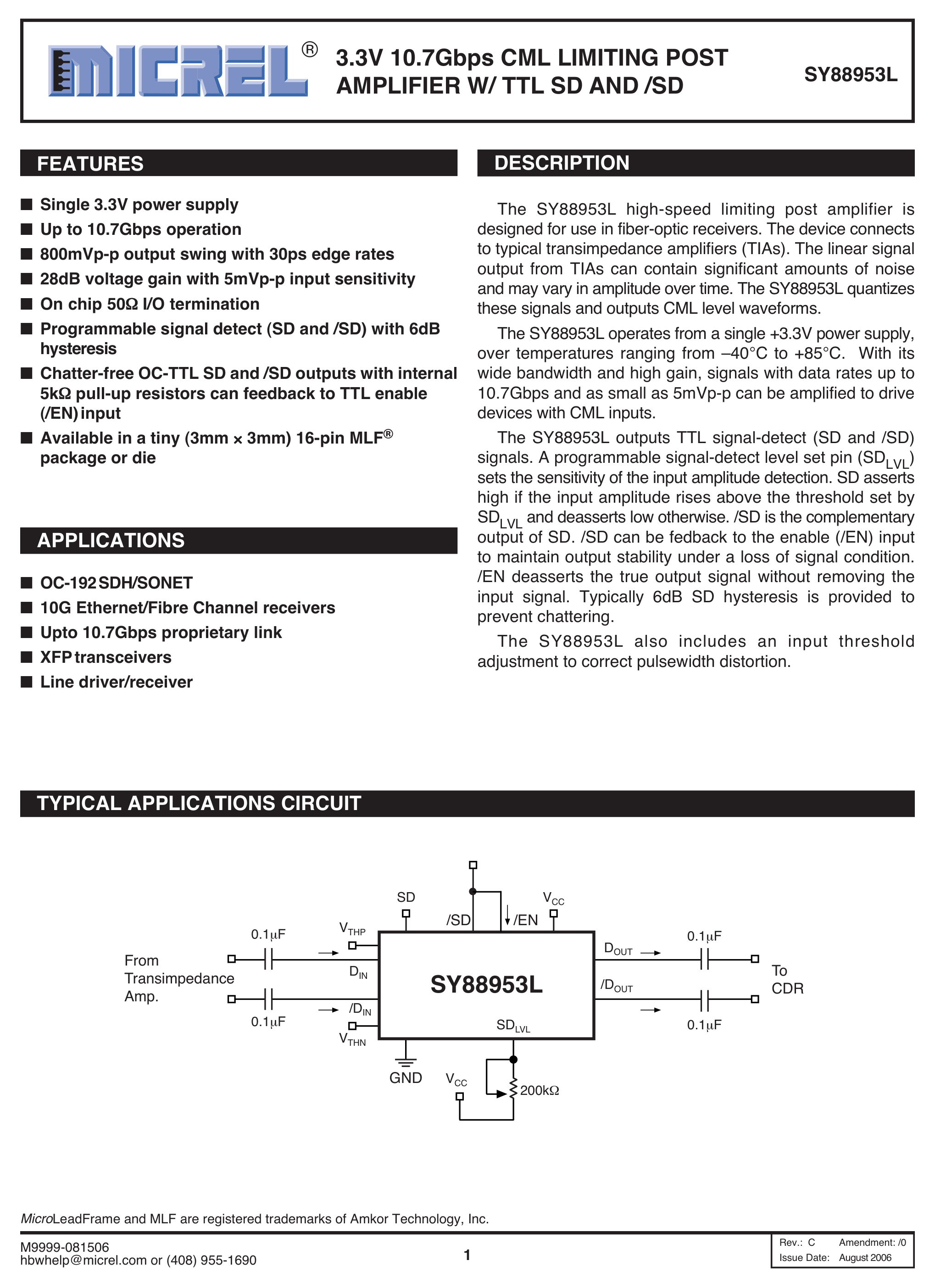
6. Application SchematicSCHEMATIC
SY88953LMI (MLF-16(3x3)) - 6. Application Schematic
Typical Application SchematicExpand ›
Original Datasheet Pinouts & Technical Drawings (7 figures · Page 1/1)
Showing 1–7 of 7 uncropped original figures for SY88953
P9 · p09_fig01EXACT PACKAGE
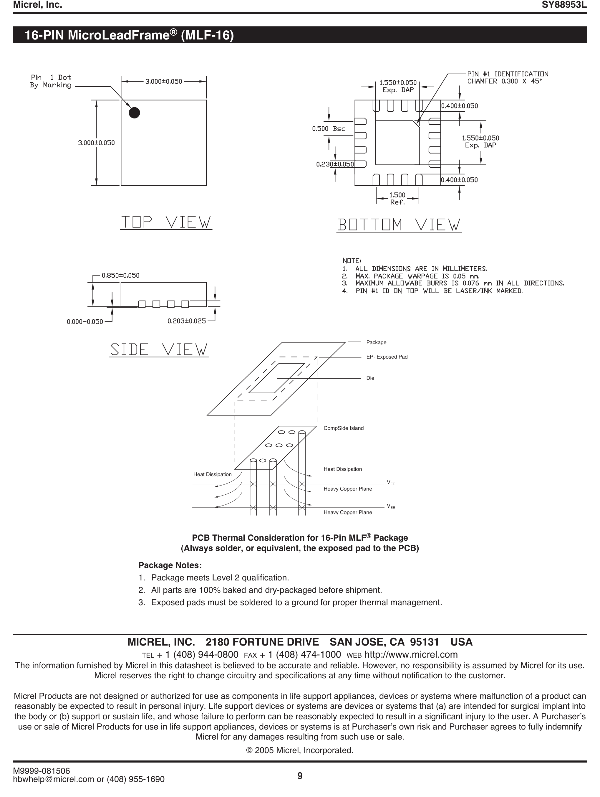
SY88953LMI (MLF-16(3x3)) — 9 | SY88953L Micrel, Inc. | M9999-081506 hbwhelp@micrel.com or (408) 955-1690 | 16-PIN MicroLeadFrame® (MLF-16) | MICREL, INC. 2180 FORTUNE DRIVE SAN JOSE, CA 95131 USA | Micrel reserves the right to change circuitry and specifications at a
9 | SY88953L Micrel, Inc. | M9999-081506 hbwhelp@micrel.com or (408) 955-1690 | 16-PIN MicroLeadFrame® (MLF-16) | MICREL, INC. 2180 FORTUNE DRIVE SAN JOSE, CA 95131 USA | Micrel reserves the right to change circuitry and specifications at a
P1 · p01_fig012038×2808px
SY88953LMI (MLF-16(3x3)) — 1 | SY88953L Micrel, Inc. | M9999-081506 hbwhelp@micrel.com or (408) 955-1690 | 3.3V 10.7Gbps CML LIMITING POST AMPLIFIER W/ TTL SD AND /SD SY88953L | Rev.: C Amendment: /0 | Issue Date: August 2006 | TYPICAL APPLICATIONS CIRCUIT | APPLICAT
1 | SY88953L Micrel, Inc. | M9999-081506 hbwhelp@micrel.com or (408) 955-1690 | 3.3V 10.7Gbps CML LIMITING POST AMPLIFIER W/ TTL SD AND /SD SY88953L | Rev.: C Amendment: /0 | Issue Date: August 2006 | TYPICAL APPLICATIONS CIRCUIT | APPLICAT
P1 · p01_fig01P1
SY88953LMI (MLF-16(3x3)) — Datasheet Page 1 (p01_fig01)
Datasheet Page 1 (p01_fig01)
P2 · p02_fig012039×2705px
SY88953LMI (MLF-16(3x3)) — 2 | SY88953L Micrel, Inc. | M9999-081506 hbwhelp@micrel.com or (408) 955-1690 | PACKAGE/ORDERING INFORMATION | PIN DESCRIPTION | Pin Number Pin Name Type Pin Function | 1 DIN Data Input True data input w/50Ω resistor to VCC. | 2, 3, 10, 11
2 | SY88953L Micrel, Inc. | M9999-081506 hbwhelp@micrel.com or (408) 955-1690 | PACKAGE/ORDERING INFORMATION | PIN DESCRIPTION | Pin Number Pin Name Type Pin Function | 1 DIN Data Input True data input w/50Ω resistor to VCC. | 2, 3, 10, 11
P7 · p07_fig012038×2705px
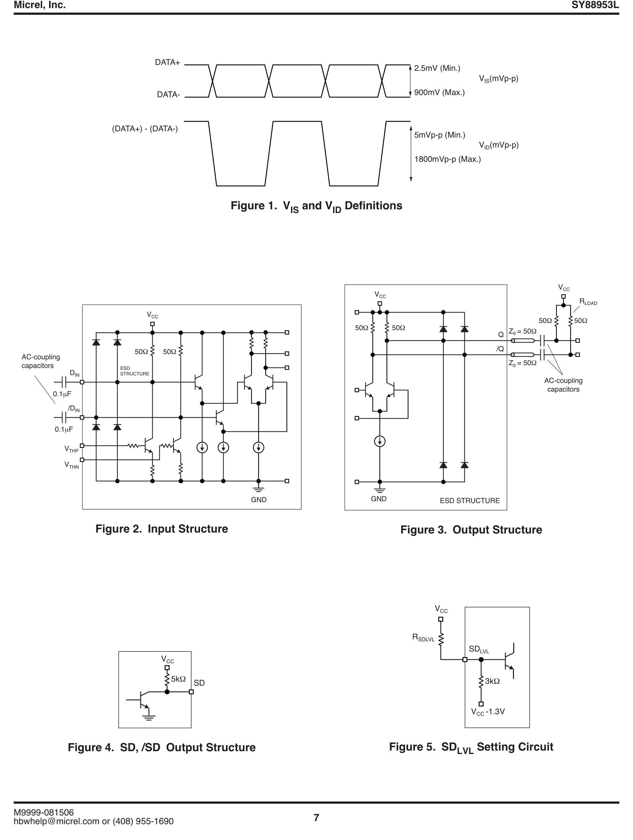
SY88953LMI (MLF-16(3x3)) — Figure 4. SD, /SD Output Structure
Figure 4. SD, /SD Output Structure
P8 · p08_fig012038×2705px
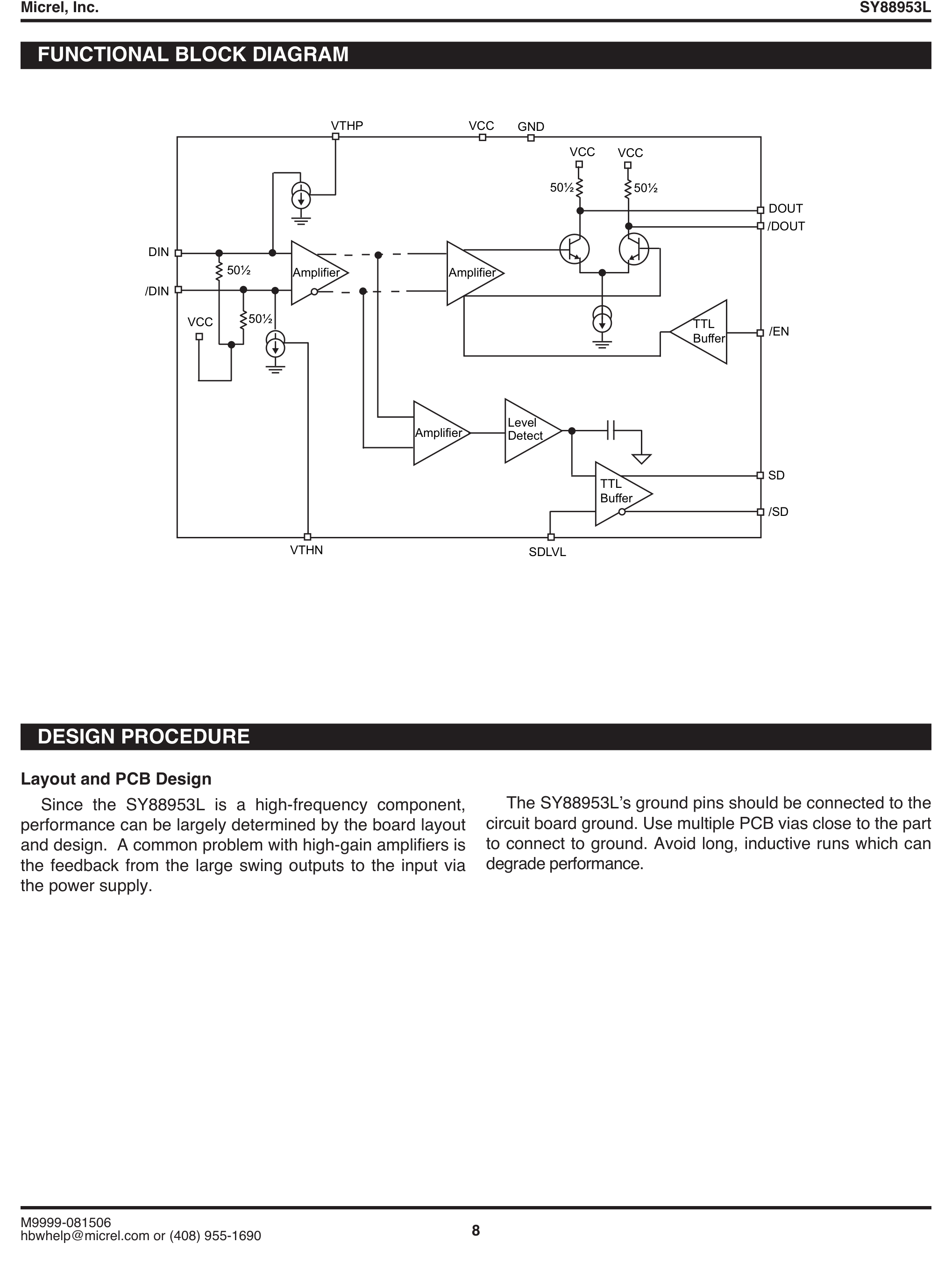
SY88953LMI (MLF-16(3x3)) — 8 | SY88953L Micrel, Inc. | M9999-081506 hbwhelp@micrel.com or (408) 955-1690 | FUNCTIONAL BLOCK DIAGRAM | Layout and PCB Design | DESIGN PROCEDURE | The SY88953L’s ground pins should be connected to the circuit board ground. Use multiple P
8 | SY88953L Micrel, Inc. | M9999-081506 hbwhelp@micrel.com or (408) 955-1690 | FUNCTIONAL BLOCK DIAGRAM | Layout and PCB Design | DESIGN PROCEDURE | The SY88953L’s ground pins should be connected to the circuit board ground. Use multiple P
P9 · p09_fig01P9
SY88953LMI (MLF-16(3x3)) — Datasheet Page 9 (p09_fig01)
Datasheet Page 9 (p09_fig01)

Technical Specifications & Part Details (SY88953LMI)

Summary of electrical parameters, mechanical dimensions, voltage range and peripheral interfaces from Datasheet (EN)
Standard Electronic & Interconnect Component
Detailed Overview:SY88953LMI (MLF-16(3x3)) is a 16-pin standard electronic & interconnect component featuring a 3.00 × 3.00 × 1.00 mm mechanical envelope (lead pitch e = 0.50 mm). Rated for 3.0V to 3.6V supply operation across 40°C to +85°C with integrated Standard I/O / Passive interfaces.
Operating Supply VoltageV_CC / V_DD
3.0V to 3.6V
Place 100nF + 10µF X7R decoupling capacitors < 2mm from supply pins
Ambient Operating TemperatureT_A
40°C to +85°C
Industrial temperature grade; T_J(max) = +125°C
Clock / RF Operating Frequencyf_CLK / f_RF
7.5 GHz
Extracted from authoritative PDF specification tables
Current & Power RatingI_OUT / I_CC
I_GPIO(max) = ±20 mA / pin | I_VDD(total) ≤ 150 mA
Observe per-pin absolute maximum current limits
Package Envelope (D × E × A)D × E × A
3.00 × 3.00 × 1.00 mm (A1=0.02 mm)
Package family: OTHER (MLF-16(3x3))
Pin Count & Lead PitchN / e
16 Pins | Pitch e = 0.50 mm (19.7 mil)
Normalized to Center-to-Center Span C per IPC-7351B
Integrated Peripheral InterfacesBuses
Standard I/O / Passive
Cross-linked with 4D Pinout & Schematic Symbol
Reflow & Moisture SensitivityIPC / MSL
IPC-7351B Level B | J-STD-020 (Peak 260°C) | MSL-3
60% windowed solder paste stencil on thermal EPAD
Engineering Safety Alert: Verify Pin-1 chamfer orientation on Top Silkscreen prior to SMT pick-and-place assembly.
Engineering Safety Alert: Connect exposed thermal pad (if present) to internal ground plane via 0.3mm stitched thermal vias.

5-Point Standards Verification

Automated compliance checks prior to export
5/5 PASS
IEEE-315 Symbol17 auto-grouped pins
OK
IPC-7351B Land Pattern17 pads · Pitch 0.50mm
OK
IPC-7525 60% Solder PasteEPAD 1.60×1.60mm windowed grid
OK
DFM Rules JLCPCB / PCBWayMin pad clearance: 0.25mm
OK
3D STEP AP214 & GLBAligned coordinate origin (0,0,0)
OK

Hardware Verification & Community Engineering Reviews

Summary of electrical parameters, mechanical dimensions, voltage range and peripheral interfaces from Datasheet
5.00 PCB Verified

Mechanical Dimensions & Land Pattern (MLF-16(3x3))

Extracted from Datasheet & IPC-7351B Normalized
mm
Package Body (D × E)Nominal
3.00 × 3.00 mm
Height (A) & Pitch (e)IPC-7351B
A=1.00mm · e=0.50mm
Pad Size (W × L)Level B
0.30 × 0.65 mm
Pins / Total PadsTopology
17P / 17Pad (CUSTOM_ARRAY)

Recommended Companion BOM & Drop-In Equivalents

Passive external components per reference schematic and 1:1 pin-compatible alternatives
DFM READY
Designator / Replacement MPNValue / PackageFunction & PCB Layout Rule
N/A
BOM
Per application circuit
MLF-16(3x3)
Size power & signal trace widths for rated load current following IPC-2221 clearance rules.

Technical Frequently Asked Questions (FAQ) — SY88953LMI (MLF-16(3x3))

Quick answers covering Pinout, IPC-7351B Land Pattern dimensions, and CAD export formats
IPC-7351B / IEEE-315

What is the Pinout and operating voltage specification of SY88953LMI (MLF-16(3x3))?

Manufactured by MICROCHIP, the SY88953LMI is housed in a MLF-16(3x3) package with 17 pins and a 0.50 mm lead pitch, supporting a VCC supply range of 3.0V to 3.6V. Key pins include: 1 (DIN: Multiplexed I/O & Peripheral Pin DIN (General)), 2 (VCC: Power Supply Input (VCC — 3.0V to 3.6V)), 3 (VCC: Power Supply Input (VCC — 3.0V to 3.6V)), 4 (/DIN: Multiplexed I/O & Peripheral Pin /DIN (General)), 5 (VTHN: Multiplexed I/O & Peripheral Pin VTHN (General)), 6 (SD: Multiplexed I/O & Peripheral Pin SD (General)).

What are the IPC-7351B PCB Footprint dimensions for SY88953LMI?

Normalized from the official datasheet mechanical drawing per IPC-7351B (Density Level B Nominal), SY88953LMI (MLF-16(3x3)) has a nominal body envelope of 3.00 × 3.00 mm, pitch e = 0.50 mm, and 17 copper pads plus a central exposed thermal pad (EPAD) of 1.60 × 1.60 mm with a 60% IPC-7525 windowed solder paste grid.

Where can I download KiCad (.kicad_mod, .kicad_sym), Fusion 360 (.lbr), and 3D STEP models for SY88953LMI?

You can download the verified open-hardware (CERN-OHL-P-2.0) CAD library bundle for SY88953LMI (MICROCHIP, MLF-16(3x3)) directly on this page, including KiCad 8 Footprints (.kicad_mod), Schematic Symbols (.kicad_sym), Autodesk Fusion 360 / Eagle (.lbr), and 3D STEP AP214 / WebGL GLB models.

Static Reference Appendix: Pinout Table (17 pins) & SY88953 Family VariantsExpand static table
Pin #Signal NameElectrical TypeFunctional Description & Design Notes
1DINDigital_IOSignal terminal DIN (I/O, 3.0V to 3.6V domain). Multiplexed alternate functions: DIN. Supported peripheral buses: General.
2VCCPower_InPrimary positive power supply input (VCC) operating in the 3.0V to 3.6V domain (Max rating: 3.6V).
3VCCPower_InPrimary positive power supply input (VCC) operating in the 3.0V to 3.6V domain (Max rating: 3.6V).
4/DINDigital_IOSignal terminal /DIN (I/O, 3.0V to 3.6V domain). Multiplexed alternate functions: /DIN. Supported peripheral buses: General.
5VTHNDigital_IOSignal terminal VTHN (I/O, 3.0V to 3.6V domain). Multiplexed alternate functions: VTHN. Supported peripheral buses: General.
6SDDigital_IOSignal terminal SD (I/O, 3.0V to 3.6V domain). Multiplexed alternate functions: SD. Supported peripheral buses: General.
7/SDDigital_IOSignal terminal /SD (I/O, 3.0V to 3.6V domain). Multiplexed alternate functions: /SD. Supported peripheral buses: General.
8GNDGND0V electrical ground return terminal (GND) for internal core logic, I/O drivers, and analog sub-blocks.
9/DOUTDigital_IOSignal terminal /DOUT (I/O, 3.0V to 3.6V domain). Multiplexed alternate functions: /DOUT. Supported peripheral buses: General.
10VCCPower_InPrimary positive power supply input (VCC) operating in the 3.0V to 3.6V domain (Max rating: 3.6V).
11VCCPower_InPrimary positive power supply input (VCC) operating in the 3.0V to 3.6V domain (Max rating: 3.6V).
12DOUTDigital_IOSignal terminal DOUT (I/O, 3.0V to 3.6V domain). Multiplexed alternate functions: DOUT. Supported peripheral buses: General.
13GNDGND0V electrical ground return terminal (GND) for internal core logic, I/O drivers, and analog sub-blocks.
14SDLVLDigital_IOSignal terminal SDLVL (I/O, 3.0V to 3.6V domain). Multiplexed alternate functions: SDLVL. Supported peripheral buses: General.
15/ENDigital_IOSignal terminal /EN (I/O, 3.0V to 3.6V domain). Multiplexed alternate functions: /EN. Supported peripheral buses: General.
16VTHPDigital_IOSignal terminal VTHP (I/O, 3.0V to 3.6V domain). Multiplexed alternate functions: VTHP. Supported peripheral buses: General.
17EPGNDBottom exposed die attach pad (EP) providing primary thermal conduction path to the PCB and low-inductance 0V ground return.