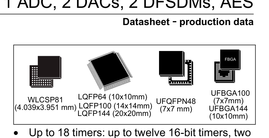
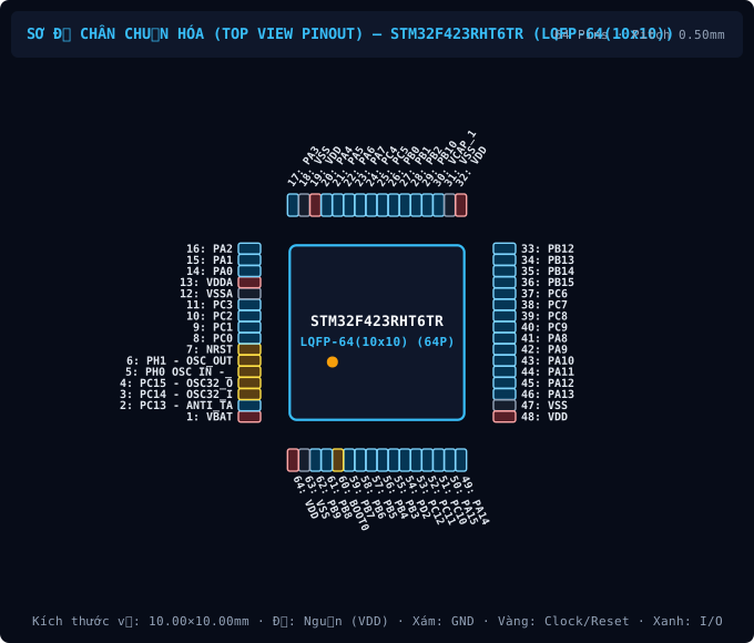
LQFP-64(10x10) · 64P
IPC-7351B
64P10.0×10.0×1.60mmP=0.5mm
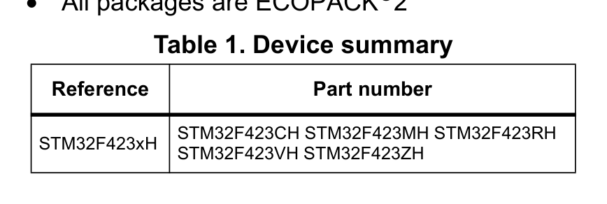
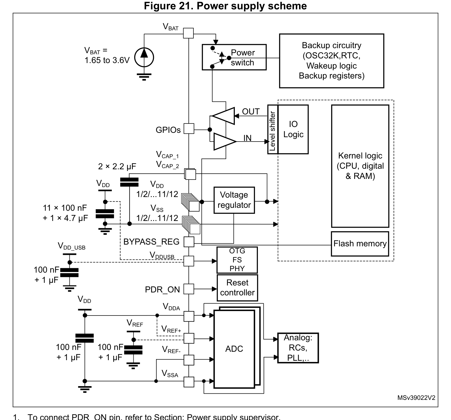
STM32F423 (LQFP-64(10x10))
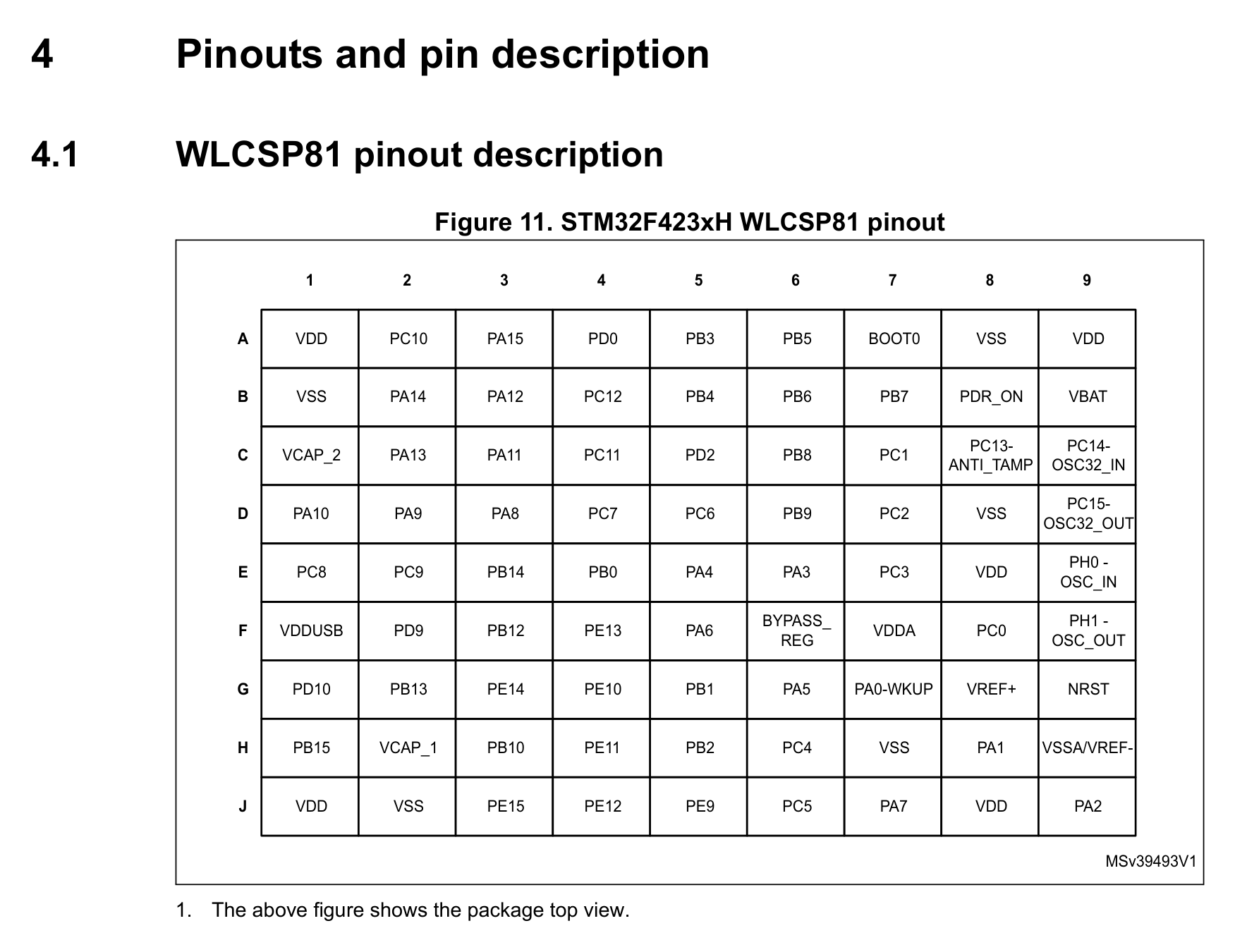
| Pin | Symbol | Type | Function (EN) |
|---|---|---|---|
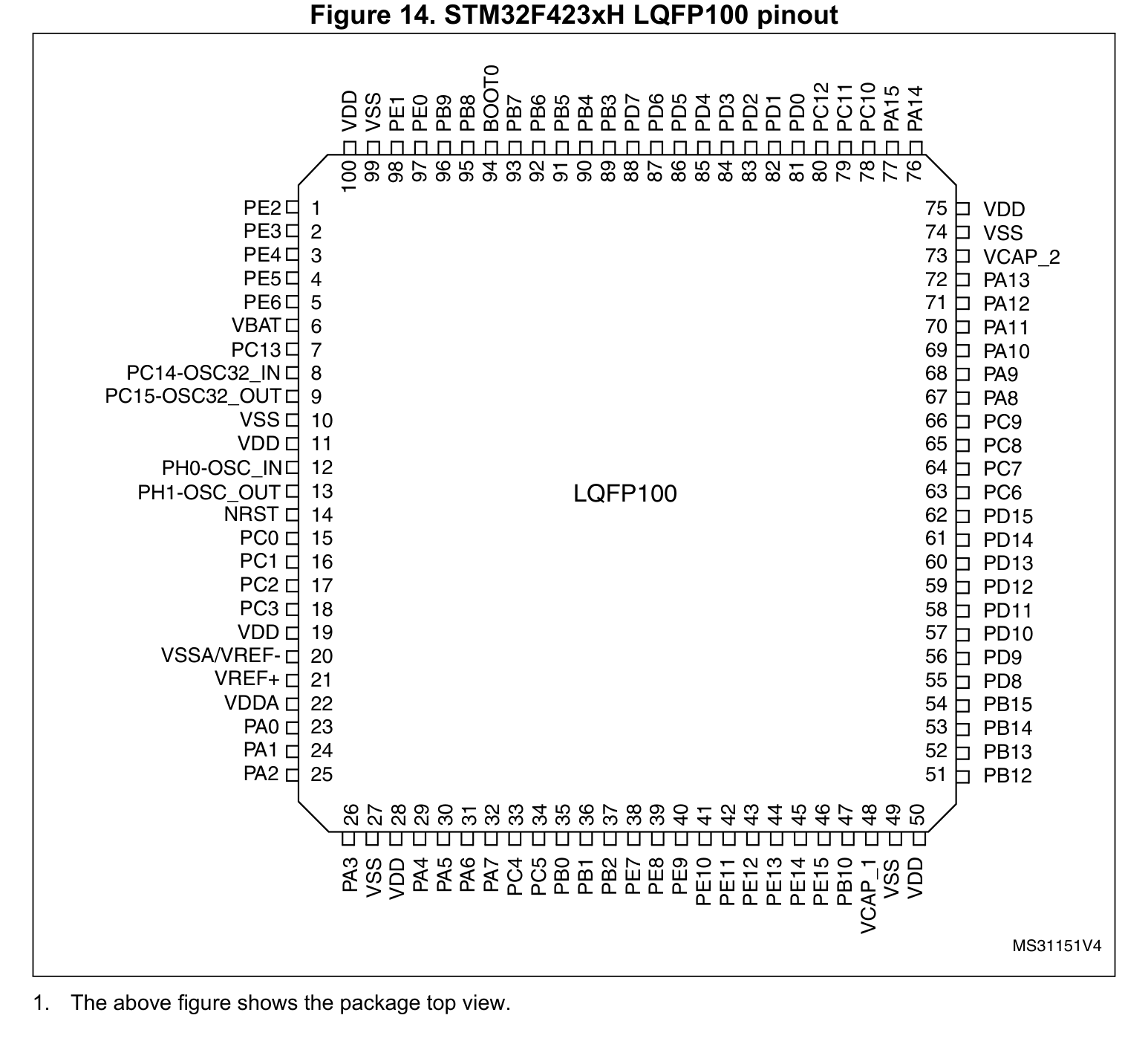
| 1 | PE2 | I/O | Multiplexed I/O & Peripheral Pin PE2 (UART, SPI) |
| 2 | PE3 | I/O | Multiplexed I/O & Peripheral Pin PE3 (UART) |
| 3 | PE4 | I/O | Multiplexed I/O & Peripheral Pin PE4 (SPI, I2C) |
| 4 | PE5 | I/O | Multiplexed I/O & Peripheral Pin PE5 (SPI) |
| 5 | PE6 | I/O | Multiplexed I/O & Peripheral Pin PE6 (SPI) |
| 6 | VBAT | Power | Power Supply Input (VBAT — 3.3V VDD (Max 4.0V)) |
| 7 | PC13 - ANTI_TAMP | I/O | Multiplexed I/O & Peripheral Pin PC13 - ANTI_TAMP (General) |
| 8 | PC14 - OSC32_IN | I/O | Multiplexed I/O & Peripheral Pin PC14 - OSC32_IN (RTC/CLK) |
| 9 | PC15 - OSC32_OUT | I/O | Multiplexed I/O & Peripheral Pin PC15 - OSC32_OUT (RTC/CLK) |
| 10 | VSS | GND | Ground Reference Pin (VSS) |
| 11 | VDD | Power | Power Supply Input (VDD — 3.3V VDD (Max 4.0V)) |
| 12 | PH0 OSC IN -_ | I/O | Multiplexed I/O & Peripheral Pin PH0 OSC IN -_ (RTC/CLK) |
| 13 | PH1 - OSC_OUT | I/O | Multiplexed I/O & Peripheral Pin PH1 - OSC_OUT (RTC/CLK) |
| 14 | NRST | I | System Enable & Hardware Reset (NRST) |
| 15 | PC0 | I/O | Multiplexed I/O & Peripheral Pin PC0 (ADC) |
| 16 | PC1 | I/O | Multiplexed I/O & Peripheral Pin PC1 (ADC) |
| 17 | PC2 | I/O | Multiplexed I/O & Peripheral Pin PC2 (SPI, ADC) |
| 18 | PC3 | I/O | Multiplexed I/O & Peripheral Pin PC3 (SPI, ADC) |
| 19 | VDD | Power | Power Supply Input (VDD — 3.3V VDD (Max 4.0V)) |
| 20 | VSSA | GND | Ground Reference Pin (VSSA) |
| 21 | VREF+ | Analog | Multiplexed I/O & Peripheral Pin VREF+ (General) |
| 22 | VDDA | Power | Power Supply Input (VDDA — 3.3V VDD (Max 4.0V)) |
| 23 | PA0 | I/O | Multiplexed I/O & Peripheral Pin PA0 (UART, ADC, PWM) |
| 24 | PA1 | I/O | Multiplexed I/O & Peripheral Pin PA1 (UART, SPI, ADC, PWM) |
| 25 | PA2 | I/O | Multiplexed I/O & Peripheral Pin PA2 (UART, ADC, PWM) |
| 26 | PA3 | I/O | Multiplexed I/O & Peripheral Pin PA3 (UART, ADC, PWM) |
| 27 | VSS | GND | Ground Reference Pin (VSS) |
| 28 | VDD | Power | Power Supply Input (VDD — 3.3V VDD (Max 4.0V)) |
| 29 | PA4 | I/O | Multiplexed I/O & Peripheral Pin PA4 (UART, SPI, ADC, DAC) |
| 30 | PA5 | I/O | Multiplexed I/O & Peripheral Pin PA5 (SPI, ADC, DAC, PWM) |
| 31 | PA6 | I/O | Multiplexed I/O & Peripheral Pin PA6 (SPI, ADC) |
| 32 | PA7 | I/O | Multiplexed I/O & Peripheral Pin PA7 (SPI, ADC, PWM) |
| 33 | PC4 | I/O | Multiplexed I/O & Peripheral Pin PC4 (ADC) |
| 34 | PC5 | I/O | Multiplexed I/O & Peripheral Pin PC5 (UART, I2C, ADC) |
| 35 | PB0 | I/O | Multiplexed I/O & Peripheral Pin PB0 (SPI, ADC, PWM) |
| 36 | PB1 | I/O | Multiplexed I/O & Peripheral Pin PB1 (SPI, ADC, PWM) |
| 37 | PB2 | I/O | Multiplexed I/O & Peripheral Pin PB2 (General) |
| 38 | PE7 | I/O | Multiplexed I/O & Peripheral Pin PE7 (UART) |
| 39 | PE8 | I/O | Multiplexed I/O & Peripheral Pin PE8 (UART, PWM) |
| 40 | PE9 | I/O | Multiplexed I/O & Peripheral Pin PE9 (PWM) |
| 41 | PE10 | I/O | Multiplexed I/O & Peripheral Pin PE10 (PWM) |
| 42 | PE11 | I/O | Multiplexed I/O & Peripheral Pin PE11 (SPI, PWM) |
| 43 | PE12 | I/O | Multiplexed I/O & Peripheral Pin PE12 (SPI, PWM) |
| 44 | PE13 | I/O | Multiplexed I/O & Peripheral Pin PE13 (SPI, PWM) |
| 45 | PE14 | I/O | Multiplexed I/O & Peripheral Pin PE14 (SPI, PWM) |
| 46 | PE15 | I/O | Multiplexed I/O & Peripheral Pin PE15 (General) |
| 47 | PB10 | I/O | Multiplexed I/O & Peripheral Pin PB10 (UART, SPI, I2C, PWM) |
| 48 | VCAP_1 | I/O | Multiplexed I/O & Peripheral Pin VCAP_1 (General) |
| 49 | VSS | GND | Exposed Thermal & Ground Pad (VSS) |
| 50 | VDD | Power | Power Supply Input (VDD — 3.3V VDD (Max 4.0V)) |
| 51 | PB12 | I/O | Multiplexed I/O & Peripheral Pin PB12 (UART, SPI, I2C, CAN) |
| 52 | PB13 | I/O | Multiplexed I/O & Peripheral Pin PB13 (UART, SPI, I2C, PWM, CAN) |
| 53 | PB14 | I/O | Multiplexed I/O & Peripheral Pin PB14 (UART, SPI, I2C, PWM) |
| 54 | PB15 | I/O | Multiplexed I/O & Peripheral Pin PB15 (SPI, I2C, PWM, RTC/CLK) |
| 55 | PD8 | I/O | Multiplexed I/O & Peripheral Pin PD8 (UART) |
| 56 | PD9 | I/O | Multiplexed I/O & Peripheral Pin PD9 (UART) |
| 57 | PD10 | I/O | Multiplexed I/O & Peripheral Pin PD10 (UART) |
| 58 | PD11 | I/O | Multiplexed I/O & Peripheral Pin PD11 (UART, I2C) |
| 59 | PD12 | I/O | Multiplexed I/O & Peripheral Pin PD12 (UART, I2C, PWM) |
| 60 | PD13 | I/O | Multiplexed I/O & Peripheral Pin PD13 (I2C, PWM) |
| 61 | PD14 | I/O | Multiplexed I/O & Peripheral Pin PD14 (UART, I2C, PWM) |
| 62 | PD15 | I/O | Multiplexed I/O & Peripheral Pin PD15 (UART, I2C, PWM) |
| 63 | PC6 | I/O | Multiplexed I/O & Peripheral Pin PC6 (UART, I2C, PWM) |
| 64 | PC7 | I/O | Multiplexed I/O & Peripheral Pin PC7 (UART, SPI, I2C, PWM) |
| 65 | PC8 | I/O | Multiplexed I/O & Peripheral Pin PC8 (UART, PWM) |
| 66 | PC9 | I/O | Multiplexed I/O & Peripheral Pin PC9 (PWM, RTC/CLK) |
| 67 | PA8 | I/O | Multiplexed I/O & Peripheral Pin PA8 (USB, UART, I2C, CAN, RTC/CLK) |
| 68 | PA9 | I/O | Multiplexed I/O & Peripheral Pin PA9 (USB, UART, SPI, I2C, PWM) |
| 69 | PA10 | I/O | Multiplexed I/O & Peripheral Pin PA10 (USB, UART, SPI, PWM) |
| 70 | PA11 | I/O | Multiplexed I/O & Peripheral Pin PA11 (USB, UART, SPI, PWM, CAN) |
| 71 | PA12 | I/O | Multiplexed I/O & Peripheral Pin PA12 (USB, UART, SPI, CAN) |
| 72 | PA13 | I/O | Multiplexed I/O & Peripheral Pin PA13 (SWD/JTAG) |
| 73 | VCAP_2 | I/O | Multiplexed I/O & Peripheral Pin VCAP_2 (General) |
| 74 | VSS | GND | Ground Reference Pin (VSS) |
| 75 | VDD | Power | Power Supply Input (VDD — 3.3V VDD (Max 4.0V)) |
| 76 | PA14 | I/O | Multiplexed I/O & Peripheral Pin PA14 (SWD/JTAG) |
| 77 | PA15 | I/O | Multiplexed I/O & Peripheral Pin PA15 (UART, SPI, CAN, SWD/JTAG) |
| 78 | PC10 | I/O | Multiplexed I/O & Peripheral Pin PC10 (UART, SPI) |
| 79 | PC11 | I/O | Multiplexed I/O & Peripheral Pin PC11 (UART, SPI) |
| 80 | PC12 | I/O | Multiplexed I/O & Peripheral Pin PC12 (UART, SPI) |
| 81 | PD0 | I/O | Multiplexed I/O & Peripheral Pin PD0 (CAN) |
| 82 | PD1 | I/O | Multiplexed I/O & Peripheral Pin PD1 (CAN) |
| 83 | PD2 | I/O | Multiplexed I/O & Peripheral Pin PD2 (UART) |
| 84 | PD3 | I/O | Multiplexed I/O & Peripheral Pin PD3 (UART, SPI) |
| 85 | PD4 | I/O | Multiplexed I/O & Peripheral Pin PD4 (UART) |
| 86 | PD5 | I/O | Multiplexed I/O & Peripheral Pin PD5 (UART) |
| 87 | PD6 | I/O | Multiplexed I/O & Peripheral Pin PD6 (UART, SPI) |
| 88 | PD7 | I/O | Multiplexed I/O & Peripheral Pin PD7 (UART) |
| 89 | PB3 | I/O | Multiplexed I/O & Peripheral Pin PB3 (UART, SPI, I2C, SWD/JTAG) |
| 90 | PB4 | I/O | Multiplexed I/O & Peripheral Pin PB4 (UART, SPI, CAN) |
| 91 | PB5 | I/O | Multiplexed I/O & Peripheral Pin PB5 (UART, SPI, I2C, PWM, CAN) |
| 92 | PB6 | I/O | Multiplexed I/O & Peripheral Pin PB6 (UART, PWM) |
| 93 | PB7 | I/O | Multiplexed I/O & Peripheral Pin PB7 (UART, PWM) |
| 94 | BOOT0 | I | Input-Only Pin BOOT0 (General) |
| 95 | PB8 | I/O | Multiplexed I/O & Peripheral Pin PB8 (UART, SPI, I2C, PWM, CAN) |
| 96 | PB9 | I/O | Multiplexed I/O & Peripheral Pin PB9 (UART, SPI, I2C, PWM, CAN) |
| 97 | PE0 | I/O | Multiplexed I/O & Peripheral Pin PE0 (UART) |
| 98 | PE1 | I/O | Multiplexed I/O & Peripheral Pin PE1 (UART) |
| 99 | VSS | GND | Ground Reference Pin (VSS) |
| 100 | VDD | Power | Power Supply Input (VDD — 3.3V VDD (Max 4.0V)) |
STM32F423 (LQFP-64(10x10))
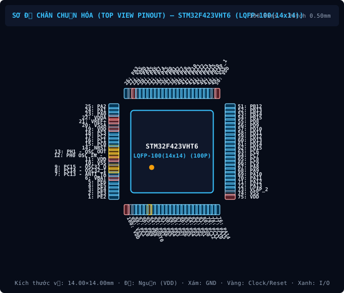
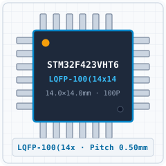
STM32F423 (LQFP-100(14x14))
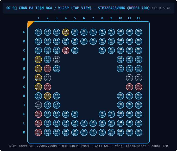
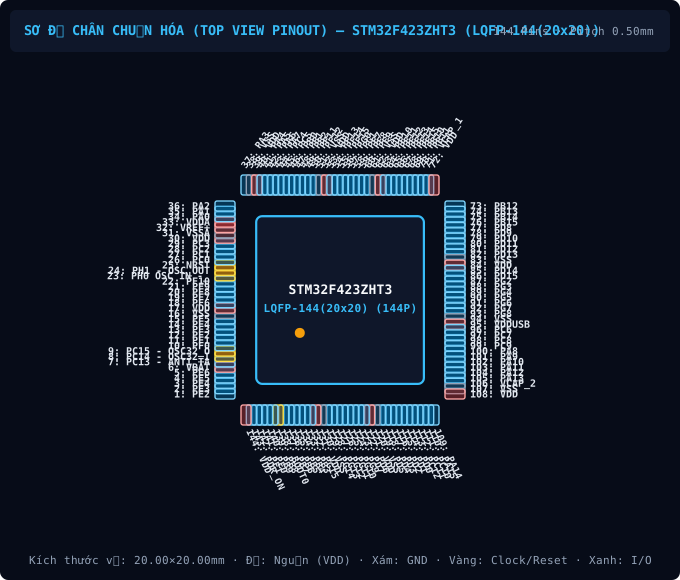
STM32F423 (LQFP-144(20x20))
| Designator / Replacement MPN | Value / Package | Function & PCB Layout Rule |
|---|---|---|
| N/A BOM | Per application circuit LQFP-100(14x14) | Size power & signal trace widths for rated load current following IPC-2221 clearance rules. |
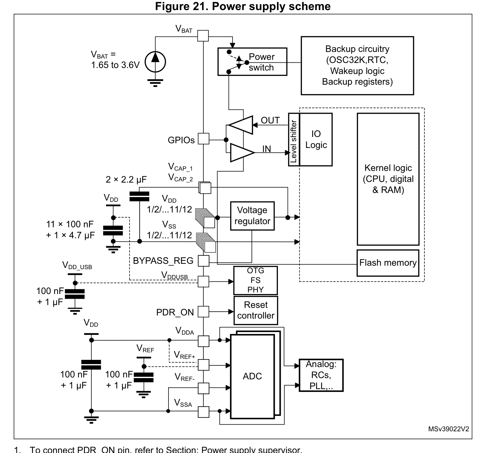
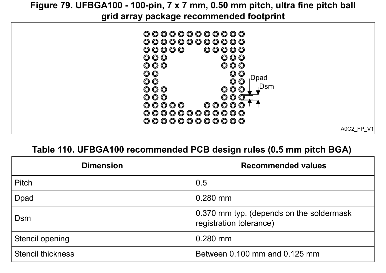
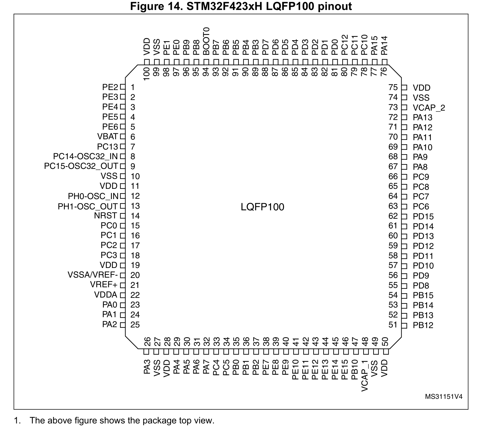
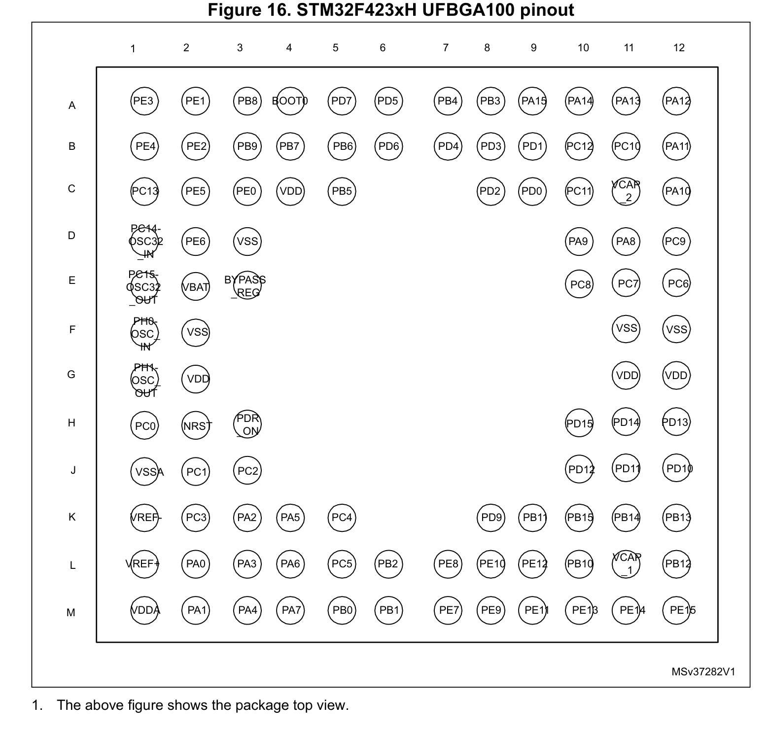
Manufactured by ST, the STM32F423VHT6 is housed in a LQFP-100(14x14) package with 100 pins and a 0.50 mm lead pitch, supporting a VCC supply range of 1.7 V to 3.6 V. Key pins include: 1 (PE2: Multiplexed I/O & Peripheral Pin PE2 (UART, SPI)), 2 (PE3: Multiplexed I/O & Peripheral Pin PE3 (UART)), 3 (PE4: Multiplexed I/O & Peripheral Pin PE4 (SPI, I2C)), 4 (PE5: Multiplexed I/O & Peripheral Pin PE5 (SPI)), 5 (PE6: Multiplexed I/O & Peripheral Pin PE6 (SPI)), 6 (VBAT: Power Supply Input (VBAT — 3.3V VDD (Max 4.0V))).
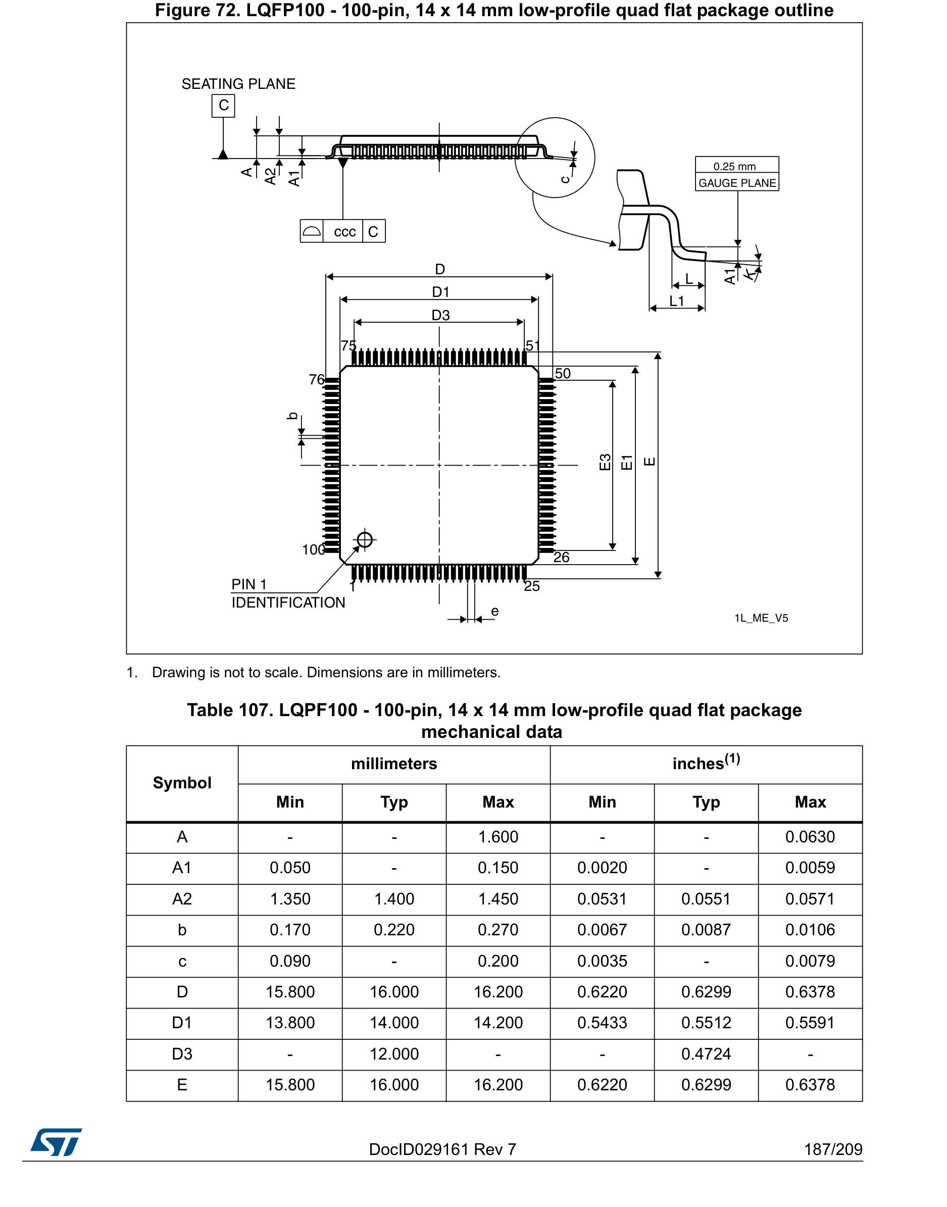
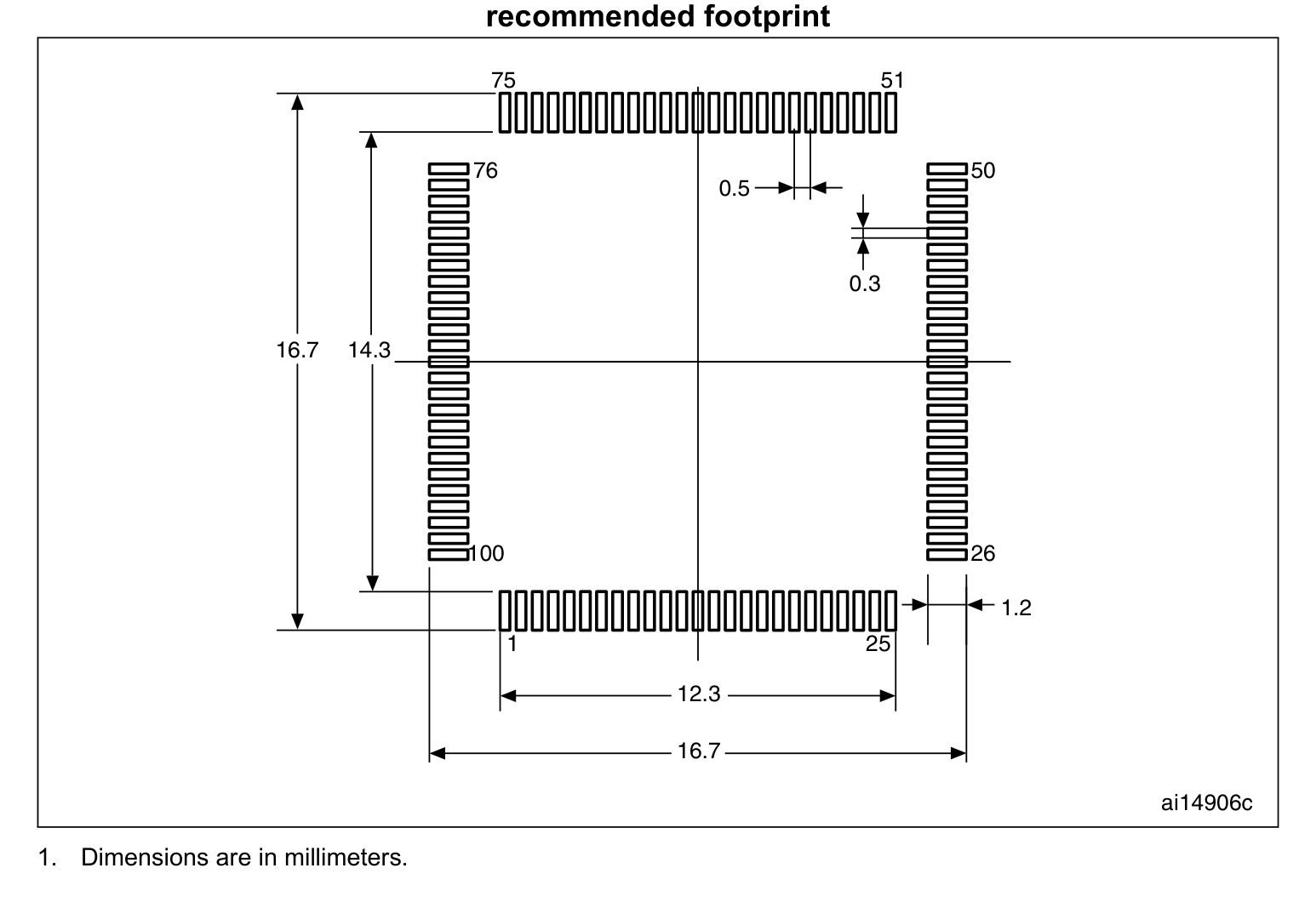
Normalized from the official datasheet mechanical drawing per IPC-7351B (Density Level B Nominal), STM32F423VHT6 (LQFP-100(14x14)) has a nominal body envelope of 14.00 × 14.00 mm, pitch e = 0.50 mm, and 100 copper pads.
You can download the verified open-hardware (CERN-OHL-P-2.0) CAD library bundle for STM32F423VHT6 (ST, LQFP-100(14x14)) directly on this page, including KiCad 8 Footprints (.kicad_mod), Schematic Symbols (.kicad_sym), Autodesk Fusion 360 / Eagle (.lbr), and 3D STEP AP214 / WebGL GLB models.
| Pin # | Signal Name | Electrical Type | Functional Description & Design Notes |
|---|---|---|---|
| 1 | PE2 | Digital_IO | Signal terminal PE2 (I/O, 3.3V VDD (5V-Tolerant FT) domain). Multiplexed alternate functions: SPI4_SCK, SPI5_SCK. Supported peripheral buses: UART, SPI. |
| 2 | PE3 | Digital_IO | Signal terminal PE3 (I/O, 3.3V VDD (5V-Tolerant FT) domain). Multiplexed alternate functions: PE3. Supported peripheral buses: UART. |
| 3 | PE4 | Digital_IO | Signal terminal PE4 (I/O, 3.3V VDD (5V-Tolerant FT) domain). Multiplexed alternate functions: SPI4_NSS, SPI5_NSS. Supported peripheral buses: SPI, I2C. |
| 4 | PE5 | Digital_IO | Signal terminal PE5 (I/O, 3.3V VDD (5V-Tolerant FT) domain). Multiplexed alternate functions: SPI4_MISO, SPI5_MISO. Supported peripheral buses: SPI. |
| 5 | PE6 | Digital_IO | Signal terminal PE6 (I/O, 3.3V VDD (5V-Tolerant FT) domain). Multiplexed alternate functions: SPI4_MOSI, SPI5_MOSI. Supported peripheral buses: SPI. |
| 6 | VBAT | Power_In | Primary positive power supply input (VBAT) operating in the 3.3V VDD (Max 4.0V) domain (Max rating: 4.0V). |
| 7 | PC13 - ANTI_TAMP | RF_50Ohm | Signal terminal PC13 - ANTI_TAMP (I/O, 3.3V VDD (5V-Tolerant FT) domain). Multiplexed alternate functions: PC13 - ANTI_TAMP. Supported peripheral buses: General. |
| 8 | PC14 - OSC32_IN | Digital_IO | Signal terminal PC14 - OSC32_IN (I/O, 3.3V VDD (5V-Tolerant FT) domain). Multiplexed alternate functions: PC14 - OSC32_IN. Supported peripheral buses: RTC/CLK. |
| 9 | PC15 - OSC32_OUT | Digital_IO | Signal terminal PC15 - OSC32_OUT (I/O, 3.3V VDD (5V-Tolerant FT) domain). Multiplexed alternate functions: PC15 - OSC32_OUT. Supported peripheral buses: RTC/CLK. |
| 10 | VSS | GND | 0V electrical ground return terminal (VSS) for internal core logic, I/O drivers, and analog sub-blocks. |
| 11 | VDD | Power_In | Primary positive power supply input (VDD) operating in the 3.3V VDD (Max 4.0V) domain (Max rating: 4.0V). |
| 12 | PH0 OSC IN -_ | Digital_IO | Signal terminal PH0 OSC IN -_ (I/O, 3.3V VDD (5V-Tolerant FT) domain). Multiplexed alternate functions: PH0 OSC IN -_. Supported peripheral buses: RTC/CLK. |
| 13 | PH1 - OSC_OUT | Digital_IO | Signal terminal PH1 - OSC_OUT (I/O, 3.3V VDD (5V-Tolerant FT) domain). Multiplexed alternate functions: PH1 - OSC_OUT. Supported peripheral buses: RTC/CLK. |
| 14 | NRST | Digital_IO | Active-low hardware reset terminal (NRST): pulling this pin Low resets the processor core and peripherals. |
| 15 | PC0 | Digital_IO | Signal terminal PC0 (I/O, 3.3V VDD (5V-Tolerant FT) domain). Multiplexed alternate functions: PC0. Supported peripheral buses: ADC. |
| 16 | PC1 | Digital_IO | Signal terminal PC1 (I/O, 3.3V VDD (5V-Tolerant FT) domain). Multiplexed alternate functions: PC1. Supported peripheral buses: ADC. |
| 17 | PC2 | Digital_IO | Signal terminal PC2 (I/O, 3.3V VDD (5V-Tolerant FT) domain). Multiplexed alternate functions: SPI2_MISO. Supported peripheral buses: SPI, ADC. |
| 18 | PC3 | Digital_IO | Signal terminal PC3 (I/O, 3.3V VDD (5V-Tolerant FT) domain). Multiplexed alternate functions: SPI2_MOSI. Supported peripheral buses: SPI, ADC. |
| 19 | VDD | Power_In | Primary positive power supply input (VDD) operating in the 3.3V VDD (Max 4.0V) domain (Max rating: 4.0V). |
| 20 | VSSA | GND | 0V electrical ground return terminal (VSSA) for internal core logic, I/O drivers, and analog sub-blocks. |
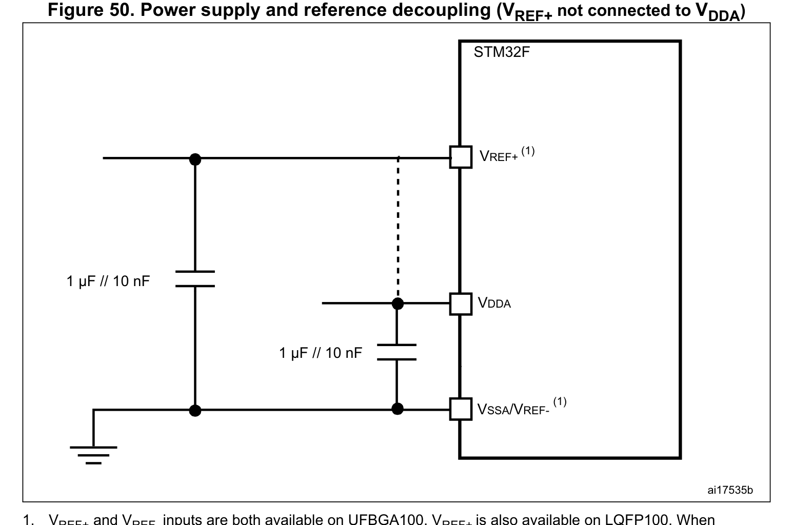
| 21 | VREF+ | Analog | Signal terminal VREF+ (Analog, 3.3V VDD (Max 4.0V) domain). Multiplexed alternate functions: VREF+. Supported peripheral buses: General. |
| 22 | VDDA | Power_In | Primary positive power supply input (VDDA) operating in the 3.3V VDD (Max 4.0V) domain (Max rating: 4.0V). |
| 23 | PA0 | Digital_IO | Signal terminal PA0 (I/O, 3.3V VDD (5V-Tolerant FT) domain). Multiplexed alternate functions: PA0. Supported peripheral buses: UART, ADC, PWM. |
| 24 | PA1 | Digital_IO | Signal terminal PA1 (I/O, 3.3V VDD (5V-Tolerant FT) domain). Multiplexed alternate functions: SPI4_MOSI. Supported peripheral buses: UART, SPI, ADC, PWM. |
| 25 | PA2 | Digital_IO | Signal terminal PA2 (I/O, 3.3V VDD (5V-Tolerant FT) domain). Multiplexed alternate functions: PA2. Supported peripheral buses: UART, ADC, PWM. |
| 26 | PA3 | Digital_IO | Signal terminal PA3 (I/O, 3.3V VDD (5V-Tolerant FT) domain). Multiplexed alternate functions: PA3. Supported peripheral buses: UART, ADC, PWM. |
| 27 | VSS | GND | 0V electrical ground return terminal (VSS) for internal core logic, I/O drivers, and analog sub-blocks. |
| 28 | VDD | Power_In | Primary positive power supply input (VDD) operating in the 3.3V VDD (Max 4.0V) domain (Max rating: 4.0V). |
| 29 | PA4 | Digital_IO | Signal terminal PA4 (I/O, 3.3V VDD (Max 4.0V) domain). Multiplexed alternate functions: SPI1_NSS, SPI3_NSS. Supported peripheral buses: UART, SPI, ADC, DAC. |
| 30 | PA5 | Digital_IO | Signal terminal PA5 (I/O, 3.3V VDD (Max 4.0V) domain). Multiplexed alternate functions: SPI1_SCK. Supported peripheral buses: SPI, ADC, DAC, PWM. |
| 31 | PA6 | Digital_IO | Signal terminal PA6 (I/O, 3.3V VDD (5V-Tolerant FT) domain). Multiplexed alternate functions: SPI1_MISOI2S2MCK. Supported peripheral buses: SPI, ADC. |
| 32 | PA7 | Digital_IO | Signal terminal PA7 (I/O, 3.3V VDD (5V-Tolerant FT) domain). Multiplexed alternate functions: SPI1_MOSI. Supported peripheral buses: SPI, ADC, PWM. |
| 33 | PC4 | Digital_IO | Signal terminal PC4 (I/O, 3.3V VDD (5V-Tolerant FT) domain). Multiplexed alternate functions: PC4. Supported peripheral buses: ADC. |
| 34 | PC5 | Digital_IO | Signal terminal PC5 (I/O, 3.3V VDD (5V-Tolerant FT) domain). Multiplexed alternate functions: PC5. Supported peripheral buses: UART, I2C, ADC. |
| 35 | PB0 | Digital_IO | Signal terminal PB0 (I/O, 3.3V VDD (5V-Tolerant FT) domain). Multiplexed alternate functions: SPI5_SCK. Supported peripheral buses: SPI, ADC, PWM. |
| 36 | PB1 | Digital_IO | Signal terminal PB1 (I/O, 3.3V VDD (5V-Tolerant FT) domain). Multiplexed alternate functions: SPI5_NSS. Supported peripheral buses: SPI, ADC, PWM. |
| 37 | PB2 | Digital_IO | Signal terminal PB2 (I/O, 3.3V VDD (5V-Tolerant FT) domain). Multiplexed alternate functions: PB2. Supported peripheral buses: General. |
| 38 | PE7 | Digital_IO | Signal terminal PE7 (I/O, 3.3V VDD (5V-Tolerant FT) domain). Multiplexed alternate functions: PE7. Supported peripheral buses: UART. |
| 39 | PE8 | Digital_IO | Signal terminal PE8 (I/O, 3.3V VDD (5V-Tolerant FT) domain). Multiplexed alternate functions: PE8. Supported peripheral buses: UART, PWM. |
| 40 | PE9 | Digital_IO | Signal terminal PE9 (I/O, 3.3V VDD (5V-Tolerant FT) domain). Multiplexed alternate functions: PE9. Supported peripheral buses: PWM. |
| 41 | PE10 | Digital_IO | Signal terminal PE10 (I/O, 3.3V VDD (5V-Tolerant FT) domain). Multiplexed alternate functions: PE10. Supported peripheral buses: PWM. |
| 42 | PE11 | Digital_IO | Signal terminal PE11 (I/O, 3.3V VDD (5V-Tolerant FT) domain). Multiplexed alternate functions: SPI4_NSS, SPI5_NSS. Supported peripheral buses: SPI, PWM. |
| 43 | PE12 | Digital_IO | Signal terminal PE12 (I/O, 3.3V VDD (5V-Tolerant FT) domain). Multiplexed alternate functions: SPI4_SCK, SPI5_SCK. Supported peripheral buses: SPI, PWM. |
| 44 | PE13 | Digital_IO | Signal terminal PE13 (I/O, 3.3V VDD (5V-Tolerant FT) domain). Multiplexed alternate functions: SPI4_MISO, SPI5_MISO. Supported peripheral buses: SPI, PWM. |
| 45 | PE14 | Digital_IO | Signal terminal PE14 (I/O, 3.3V VDD (5V-Tolerant FT) domain). Multiplexed alternate functions: SPI4_MOSI, SPI5_MOSI. Supported peripheral buses: SPI, PWM. |
| 46 | PE15 | Digital_IO | Signal terminal PE15 (I/O, 3.3V VDD (5V-Tolerant FT) domain). Multiplexed alternate functions: PE15. Supported peripheral buses: General. |
| 47 | PB10 | Digital_IO | Signal terminal PB10 (I/O, 3.3V VDD (5V-Tolerant FT) domain). Multiplexed alternate functions: SPI2_SCK. Supported peripheral buses: UART, SPI, I2C, PWM. |
| 48 | VCAP_1 | Digital_IO | Signal terminal VCAP_1 (I/O, 3.3V VDD (Max 4.0V) domain). Multiplexed alternate functions: VCAP_1. Supported peripheral buses: General. |
| 49 | VSS | GND | Bottom exposed die attach pad (VSS) providing primary thermal conduction path to the PCB and low-inductance 0V ground return. |
| 50 | VDD | Power_In | Primary positive power supply input (VDD) operating in the 3.3V VDD (Max 4.0V) domain (Max rating: 4.0V). |
| 51 | PB12 | Digital_IO | Signal terminal PB12 (I/O, 3.3V VDD (5V-Tolerant FT) domain). Multiplexed alternate functions: I2C2_SMBA, SPI2_NSS, SPI4_NSS, SPI3_SCK. Supported peripheral buses: UART, SPI, I2C, CAN. |
| 52 | PB13 | Digital_IO | Signal terminal PB13 (I/O, 3.3V VDD (5V-Tolerant FT) domain). Multiplexed alternate functions: SPI2_SCK, SPI4_SCK. Supported peripheral buses: UART, SPI, I2C, PWM, CAN. |
| 53 | PB14 | Digital_IO | Signal terminal PB14 (I/O, 3.3V VDD (5V-Tolerant FT) domain). Multiplexed alternate functions: SPI2_MISO. Supported peripheral buses: UART, SPI, I2C, PWM. |
| 54 | PB15 | Digital_IO | Signal terminal PB15 (I/O, 3.3V VDD (5V-Tolerant FT) domain). Multiplexed alternate functions: SPI2_MOSI. Supported peripheral buses: SPI, I2C, PWM, RTC/CLK. |
| 55 | PD8 | Digital_IO | Signal terminal PD8 (I/O, 3.3V VDD (5V-Tolerant FT) domain). Multiplexed alternate functions: PD8. Supported peripheral buses: UART. |
| 56 | PD9 | Digital_IO | Signal terminal PD9 (I/O, 3.3V VDD (5V-Tolerant FT) domain). Multiplexed alternate functions: PD9. Supported peripheral buses: UART. |
| 57 | PD10 | Digital_IO | Signal terminal PD10 (I/O, 3.3V VDD (5V-Tolerant FT) domain). Multiplexed alternate functions: PD10. Supported peripheral buses: UART. |
| 58 | PD11 | Digital_IO | Signal terminal PD11 (I/O, 3.3V VDD (5V-Tolerant FT) domain). Multiplexed alternate functions: PD11. Supported peripheral buses: UART, I2C. |
| 59 | PD12 | Digital_IO | Signal terminal PD12 (I/O, 3.3V VDD (5V-Tolerant FT) domain). Multiplexed alternate functions: PD12. Supported peripheral buses: UART, I2C, PWM. |
| 60 | PD13 | Digital_IO | Signal terminal PD13 (I/O, 3.3V VDD (5V-Tolerant FT) domain). Multiplexed alternate functions: PD13. Supported peripheral buses: I2C, PWM. |
| 61 | PD14 | Digital_IO | Signal terminal PD14 (I/O, 3.3V VDD (5V-Tolerant FT) domain). Multiplexed alternate functions: PD14. Supported peripheral buses: UART, I2C, PWM. |
| 62 | PD15 | Digital_IO | Signal terminal PD15 (I/O, 3.3V VDD (5V-Tolerant FT) domain). Multiplexed alternate functions: PD15. Supported peripheral buses: UART, I2C, PWM. |
| 63 | PC6 | Digital_IO | Signal terminal PC6 (I/O, 3.3V VDD (5V-Tolerant FT) domain). Multiplexed alternate functions: PC6. Supported peripheral buses: UART, I2C, PWM. |
| 64 | PC7 | Digital_IO | Signal terminal PC7 (I/O, 3.3V VDD (5V-Tolerant FT) domain). Multiplexed alternate functions: SPI2_SCK. Supported peripheral buses: UART, SPI, I2C, PWM. |