
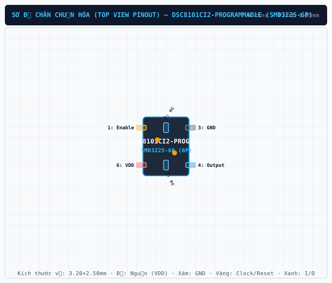
DSC8101CI2-PROGRAMMABLE (SMD3225-6P) — Symbol, Footprint IPC-7351B & 3D STEP Model

DSC8101CI2-PROGRAMMABLE

MICROCHIPID: C1323983SMD3225-6P · 6 Pins · Pitch 1.05mmIPC-7351B Verified5.0 (0)
SYNCHRONIZED 4D CROSS-PROBE MODETouch or hover any pin to highlight concurrently across Symbol, Footprint and 3D
1. SYMBOL
U1 · DSC8101CI2-PROGRAMMABLE (SMD3225-6P)1Enable2nc3GND6VDD5nc4OutputGrid Pitch = 2.54mm (IEEE-315)-20.3-15.2-10.2-5.105.110.215.220.310.25.10-5.1-10.2mm
2. 2D FOOTPRINT
463152E=3.20mm · Pitch e=1.05mmD=2.50mm-3-2-101233210-1-2-3mm
3. 3D CAD MODEL
Package Body: 3.20mm × 2.50mm · Pitch: 1.05mm · Ruler Step: 1.00mmSynced <100ms

Synchronized Pinout (Symbol / 2D / 3D) (6/6)

Touch or hover any pin to highlight concurrently across Symbol, Footprint and 3D
PinSymbolTypeFunction (EN)
1EnableI/OMultiplexed I/O & Peripheral Pin Enable (General)
2ncI/OMultiplexed I/O & Peripheral Pin nc (General)
3GNDGNDGround Reference Pin (GND)
4OutputI/OMultiplexed I/O & Peripheral Pin Output (General)
5ncI/OMultiplexed I/O & Peripheral Pin nc (General)
6VDDPowerPower Supply Input (VDD — 3.3V / 5.0V Standard Logic)
PIN 1 Enable
I/O
Multiplexed I/O & Peripheral Pin Enable (General)
Design note: Signal terminal Enable (I/O, 3.3V / 5.0V Standard Logic domain). Multiplexed alternate functions: Enable. Supported peripheral buses: General.
IPC-7351B Solder Density & Span C/G/Z Tuner

Live Embedded Datasheet PDF & Technical Drawing Gallery (6 Standard Drawings + 18 Extracted Figures)

Read the original datasheet PDF directly or click any drawing to view fullscreen
Open PDF in New Window ↗Read Datasheet PDF (.pdf)
PDF VIEWEROfficial Datasheet Document: DSC8101CI2-PROGRAMMABLE (MICROCHIP · SMD3225-6P)
Scroll, search text (Ctrl+F), or expand directly inside the embedded PDF reader below
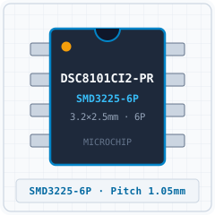
1. Realistic 3D PackageREPRESENTATIVE
DSC8101CI2-PROGRAMMABLE (SMD3225-6P) - 1. Realistic 3D Package
Detailed solid 3D bodyExpand ›
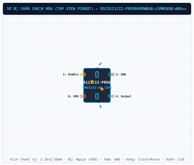
2. Standard Pinout (Top View)CLEANROOM PINOUT
DSC8101CI2-PROGRAMMABLE (SMD3225-6P) - 2. Standard Pinout (Top View)
True package pinout (6 pins)Expand ›
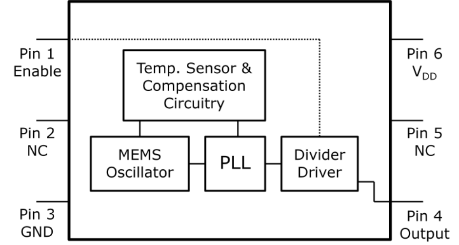
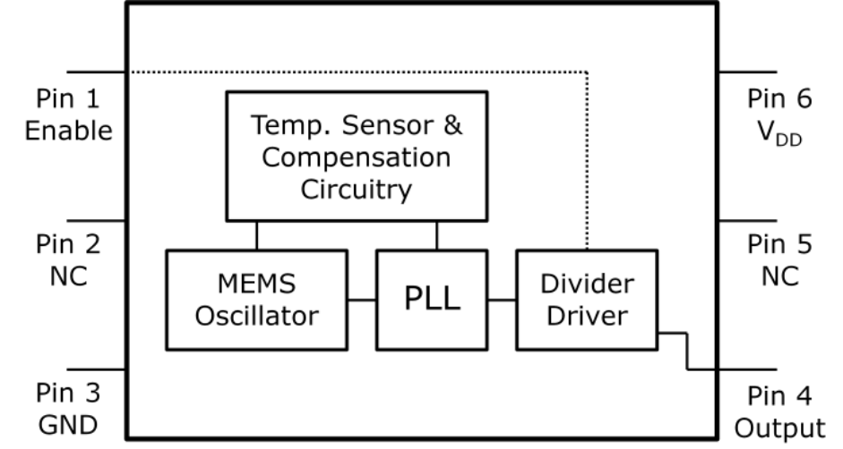
3. Original Datasheet PinoutPDF PINOUT
DSC8101CI2-PROGRAMMABLE (SMD3225-6P) - 3. Original Datasheet Pinout
Uncropped datasheet pin diagramExpand ›
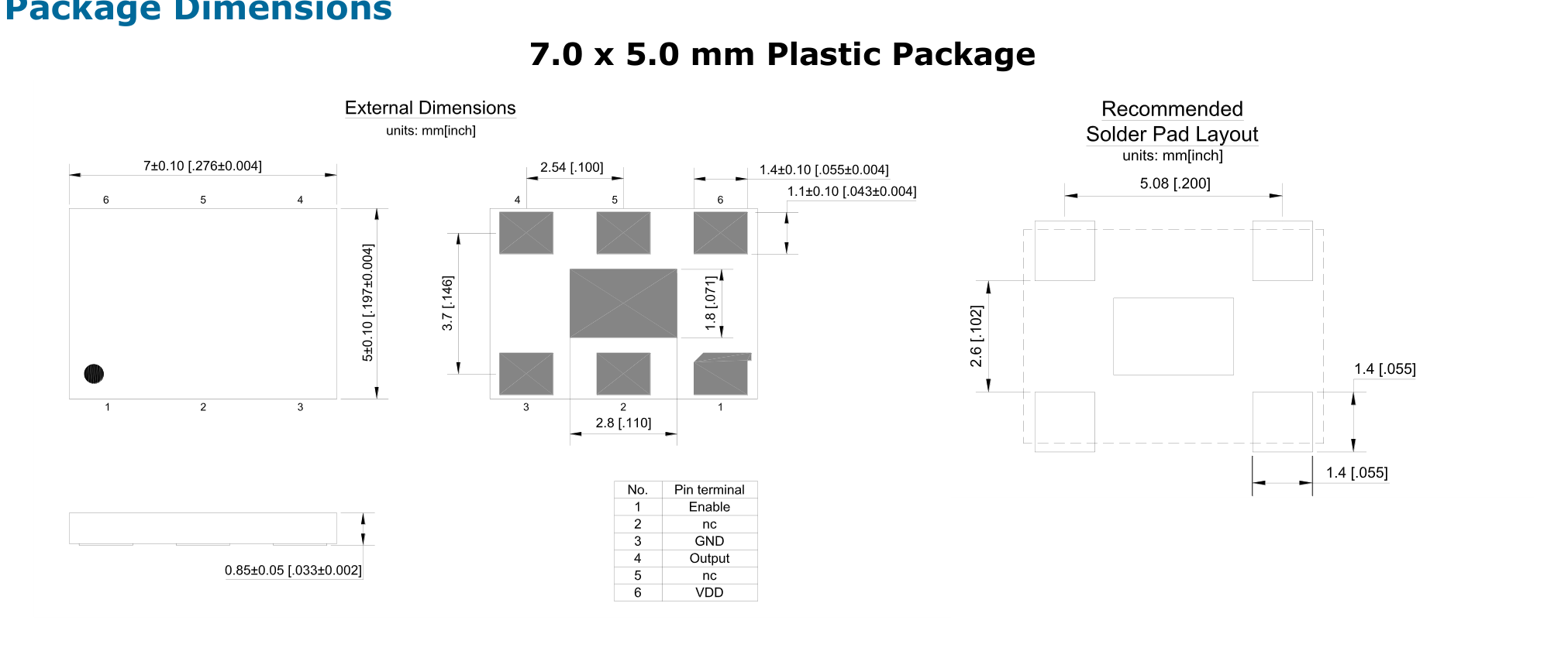
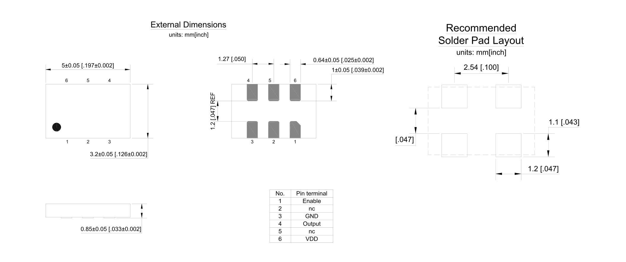
4. Package Dimensions (D×E×A)PACKAGE DIMENSIONS
DSC8101CI2-PROGRAMMABLE (SMD3225-6P) - 4. Package Dimensions (D×E×A)
SMD3225-6P · 3.20×2.50mm · Pitch 1.05mmExpand ›
5. Recommended Land PatternLAND PATTERN
DSC8101CI2-PROGRAMMABLE (SMD3225-6P) - 5. Recommended Land Pattern
IPC-7351B Footprint (6 Pads)Expand ›
6. Application SchematicSCHEMATIC
DSC8101CI2-PROGRAMMABLE (SMD3225-6P) - 6. Application Schematic
Typical Application SchematicExpand ›
Original Datasheet Pinouts & Technical Drawings (18 figures · Page 1/2)
Showing 1–12 of 18 uncropped original figures for DSC8101 / DSC8121
P1 · p01_fig012100×361px
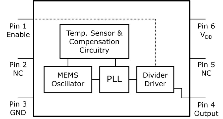
DSC8101CI2-PROGRAMMABLE (SMD3225-6P) — General Description
General Description
P1 · p01_fig02941×502px
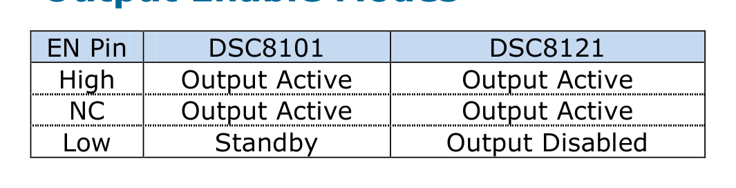
DSC8101CI2-PROGRAMMABLE (SMD3225-6P) — EN Pin DSC8101 DSC8121 High Output Active Output Active NC Output Active Output Active Low Standby Output Disabled
EN Pin DSC8101 DSC8121 High Output Active Output Active NC Output Active Output Active Low Standby Output Disabled
P1 · p01_fig031065×272px
DSC8101CI2-PROGRAMMABLE (SMD3225-6P) — Output Enable Modes
Output Enable Modes
P1 · p01_fig02P1
DSC8101CI2-PROGRAMMABLE (SMD3225-6P) — Datasheet Page 1 (p01_fig02)
Datasheet Page 1 (p01_fig02)
P2 · p02_fig012067×2346px
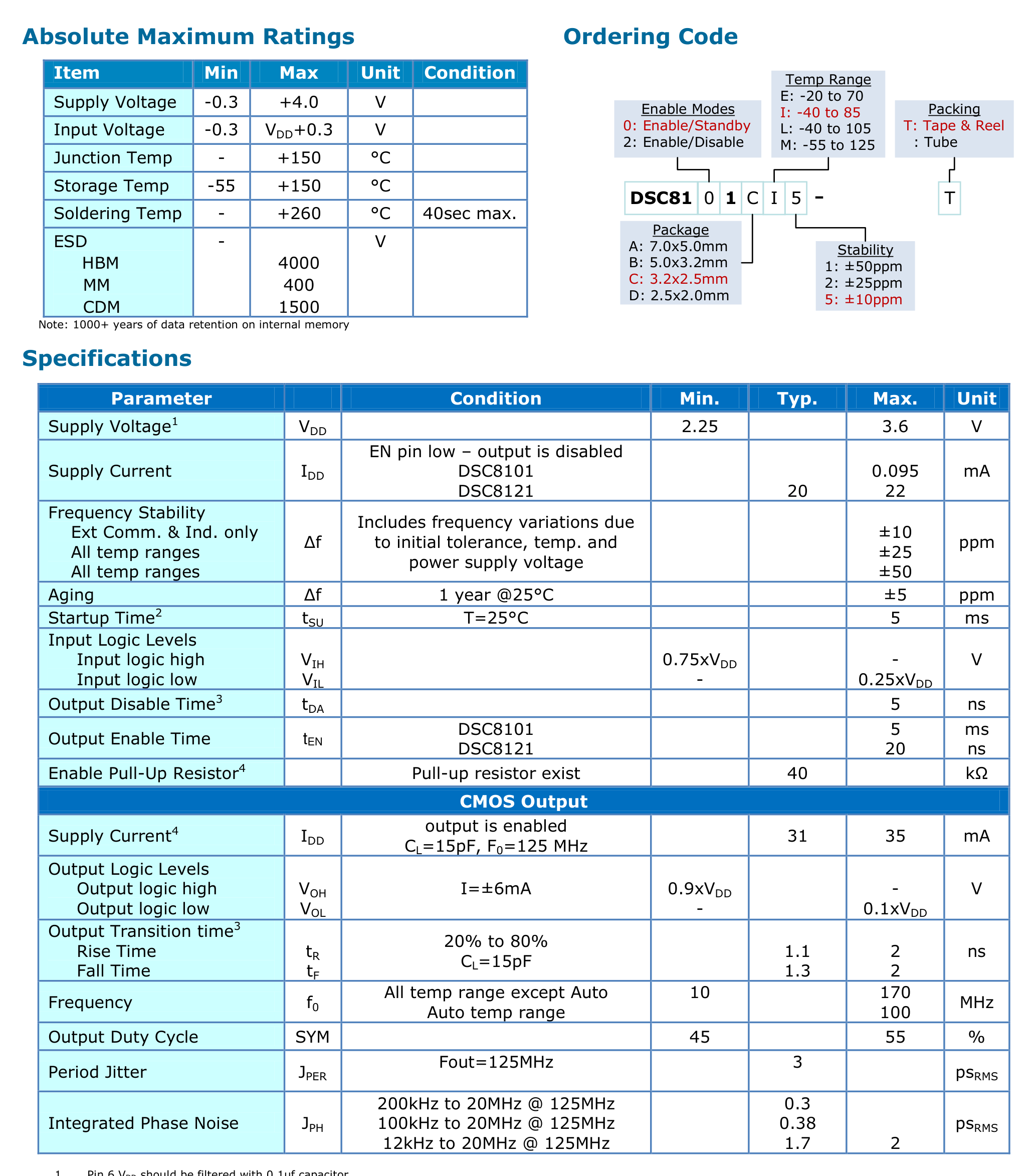
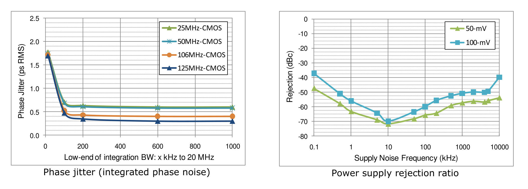
DSC8101CI2-PROGRAMMABLE (SMD3225-6P) — DSC8101 Programmable Low-Jitter Precision CMOS Oscillator DSC8112
DSC8101 Programmable Low-Jitter Precision CMOS Oscillator DSC8112
P3 · p03_fig012105×753px
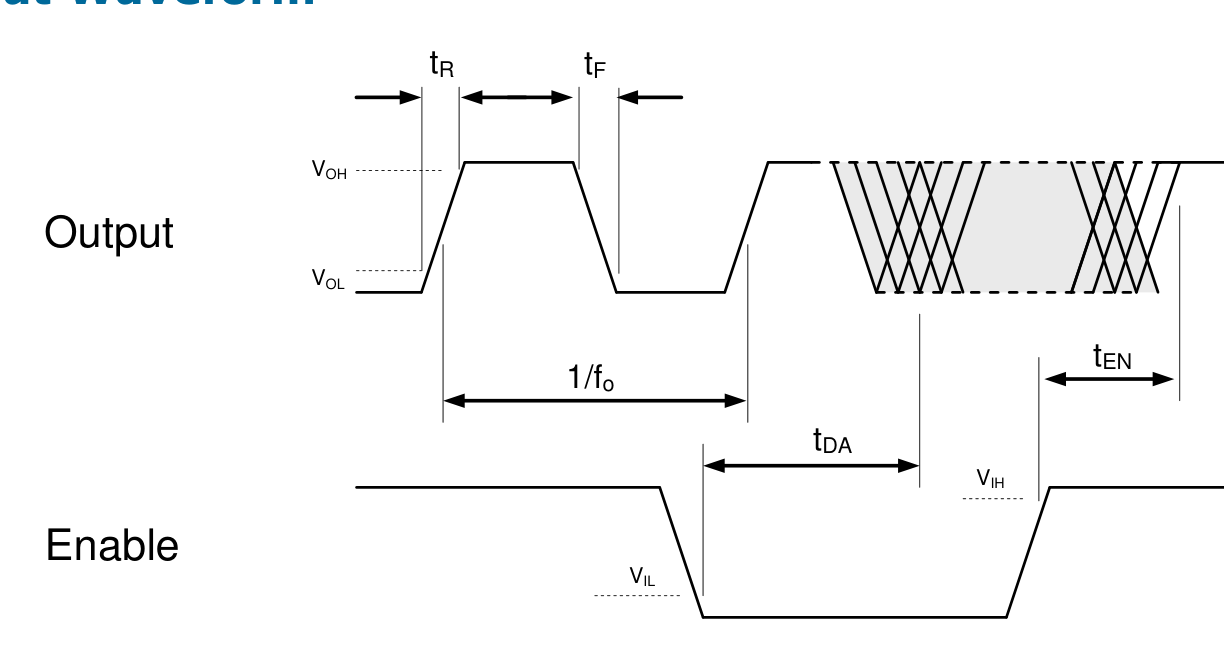
DSC8101CI2-PROGRAMMABLE (SMD3225-6P) — tF tR
tF tR
P3 · p03_fig021224×661px
DSC8101CI2-PROGRAMMABLE (SMD3225-6P) — VDD
VDD
P3 · p03_fig031192×582px
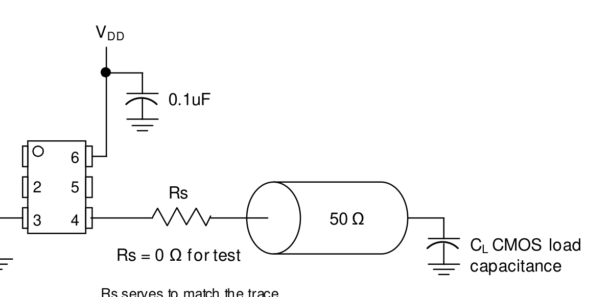
DSC8101CI2-PROGRAMMABLE (SMD3225-6P) — Typical Termination Scheme | VDD | 0.1uF | 50 Ω | Rs = 0 Ωfor test | 2 | 3 4 | 5 | 6 | Rs | Rs serves to match the trace impedances. Depending on board layout, the value may range from 0 to 30 ohms. | CL CMOS load capacitance
Typical Termination Scheme | VDD | 0.1uF | 50 Ω | Rs = 0 Ωfor test | 2 | 3 4 | 5 | 6 | Rs | Rs serves to match the trace impedances. Depending on board layout, the value may range from 0 to 30 ohms. | CL CMOS load capacitance
P3 · p03_fig01P3
DSC8101CI2-PROGRAMMABLE (SMD3225-6P) — Datasheet Page 3 (p03_fig01)
Datasheet Page 3 (p03_fig01)
P4 · p04_fig011163×476px
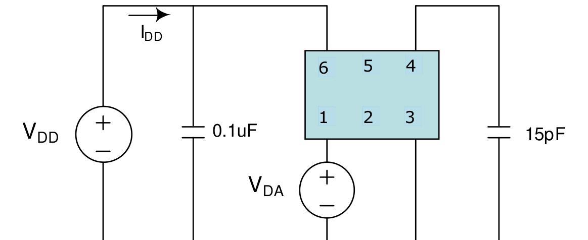
DSC8101CI2-PROGRAMMABLE (SMD3225-6P) — Test Circuit
Test Circuit
P4 · p04_fig02618×421px
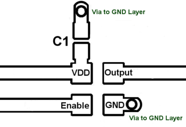
DSC8101CI2-PROGRAMMABLE (SMD3225-6P) — Board Layout (recommended)
Board Layout (recommended)
P4 · p04_fig031972×527px
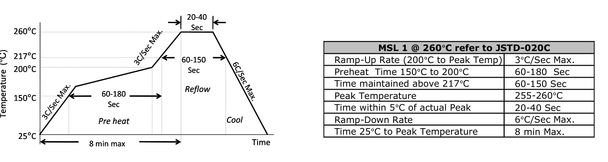
DSC8101CI2-PROGRAMMABLE (SMD3225-6P) — Solder Reflow Profile
Solder Reflow Profile
Page 1 / 2 (18 extracted figures)

Technical Specifications & Part Details (DSC8101CI2-PROGRAMMABLE)

Summary of electrical parameters, mechanical dimensions, voltage range and peripheral interfaces from Datasheet (EN)
Standard Electronic & Interconnect Component
Detailed Overview:DSC8101CI2-PROGRAMMABLE (SMD3225-6P) is a 6-pin standard electronic & interconnect component featuring a 3.20 × 2.50 × 1.00 mm mechanical envelope (lead pitch e = 1.05 mm). Rated for 1.8V ~ 5.5V (Theo Datasheet) supply operation across -40°C ~ +85°C (Industrial Grade) with integrated Standard I/O / Passive interfaces.
Operating Supply VoltageV_CC / V_DD
1.8V ~ 5.5V (Theo Datasheet)
Place 100nF + 10µF X7R decoupling capacitors < 2mm from supply pins
Ambient Operating TemperatureT_A
-40°C ~ +85°C (Industrial Grade)
Industrial temperature grade; T_J(max) = +125°C
Clock / RF Operating Frequencyf_CLK / f_RF
170 MHz
Extracted from authoritative PDF specification tables
Current & Power RatingI_OUT / I_CC
I_GPIO(max) = ±20 mA / pin | I_VDD(total) ≤ 150 mA
Observe per-pin absolute maximum current limits
Package Envelope (D × E × A)D × E × A
3.20 × 2.50 × 1.00 mm (A1=0.02 mm)
Package family: OTHER (SMD3225-6P)
Pin Count & Lead PitchN / e
6 Pins | Pitch e = 1.05 mm (41.3 mil)
Normalized to Center-to-Center Span C per IPC-7351B
Integrated Peripheral InterfacesBuses
Standard I/O / Passive
Cross-linked with 4D Pinout & Schematic Symbol
Reflow & Moisture SensitivityIPC / MSL
IPC-7351B Level B | J-STD-020 (Peak 260°C) | MSL-3
60% windowed solder paste stencil on thermal EPAD
Engineering Safety Alert: Verify Pin-1 chamfer orientation on Top Silkscreen prior to SMT pick-and-place assembly.
Engineering Safety Alert: Connect exposed thermal pad (if present) to internal ground plane via 0.3mm stitched thermal vias.

5-Point Standards Verification

Automated compliance checks prior to export
5/5 PASS
IEEE-315 Symbol6 auto-grouped pins
OK
IPC-7351B Land Pattern6 pads · Pitch 1.05mm
OK
IPC-7525 60% Solder PasteReflow 1:1 Standard
OK
DFM Rules JLCPCB / PCBWayMin pad clearance: 0.25mm
OK
3D STEP AP214 & GLBAligned coordinate origin (0,0,0)
OK

Hardware Verification & Community Engineering Reviews

Summary of electrical parameters, mechanical dimensions, voltage range and peripheral interfaces from Datasheet
5.00 PCB Verified
IPC-7351B

Family Variants & Same Datasheet Chips — DSC8101 / DSC8121 (2)

Select package variant or sibling MPN sharing this datasheet

Mechanical Dimensions & Land Pattern (SMD3225-6P)

Extracted from Datasheet & IPC-7351B Normalized
mm
Package Body (D × E)Nominal
3.20 × 2.50 mm
Height (A) & Pitch (e)IPC-7351B
A=1.00mm · e=1.05mm
Pad Size (W × L)Level B
1.00 × 1.05 mm
Pins / Total PadsTopology
6P / 6Pad (CUSTOM_ARRAY)

Recommended Companion BOM & Drop-In Equivalents

Passive external components per reference schematic and 1:1 pin-compatible alternatives
DFM READY
Designator / Replacement MPNValue / PackageFunction & PCB Layout Rule
N/A
BOM
Per application circuit
SMD3225-6P
Size power & signal trace widths for rated load current following IPC-2221 clearance rules.

Technical Frequently Asked Questions (FAQ) — DSC8101CI2-PROGRAMMABLE (SMD3225-6P)

Quick answers covering Pinout, IPC-7351B Land Pattern dimensions, and CAD export formats
IPC-7351B / IEEE-315

What is the Pinout and operating voltage specification of DSC8101CI2-PROGRAMMABLE (SMD3225-6P)?

Manufactured by MICROCHIP, the DSC8101CI2-PROGRAMMABLE is housed in a SMD3225-6P package with 6 pins and a 1.05 mm lead pitch. Key pins include: 1 (Enable: Multiplexed I/O & Peripheral Pin Enable (General)), 2 (nc: Multiplexed I/O & Peripheral Pin nc (General)), 3 (GND: Ground Reference Pin (GND)), 4 (Output: Multiplexed I/O & Peripheral Pin Output (General)), 5 (nc: Multiplexed I/O & Peripheral Pin nc (General)), 6 (VDD: Power Supply Input (VDD — 3.3V / 5.0V Standard Logic)).

What are the IPC-7351B PCB Footprint dimensions for DSC8101CI2-PROGRAMMABLE?

Normalized from the official datasheet mechanical drawing per IPC-7351B (Density Level B Nominal), DSC8101CI2-PROGRAMMABLE (SMD3225-6P) has a nominal body envelope of 2.50 × 3.20 mm, pitch e = 1.05 mm, and 6 copper pads.

Where can I download KiCad (.kicad_mod, .kicad_sym), Fusion 360 (.lbr), and 3D STEP models for DSC8101CI2-PROGRAMMABLE?

You can download the verified open-hardware (CERN-OHL-P-2.0) CAD library bundle for DSC8101CI2-PROGRAMMABLE (MICROCHIP, SMD3225-6P) directly on this page, including KiCad 8 Footprints (.kicad_mod), Schematic Symbols (.kicad_sym), Autodesk Fusion 360 / Eagle (.lbr), and 3D STEP AP214 / WebGL GLB models.

Static Reference Appendix: Pinout Table (6 pins) & DSC8101 / DSC8121 Family VariantsExpand static table
Pin #Signal NameElectrical TypeFunctional Description & Design Notes
1EnableDigital_IOSignal terminal Enable (I/O, 3.3V / 5.0V Standard Logic domain). Multiplexed alternate functions: Enable. Supported peripheral buses: General.
2ncNCSignal terminal nc (I/O, 3.3V / 5.0V Standard Logic domain). Multiplexed alternate functions: nc. Supported peripheral buses: General.
3GNDGND0V electrical ground return terminal (GND) for internal core logic, I/O drivers, and analog sub-blocks.
4OutputDigital_IOSignal terminal Output (I/O, 3.3V / 5.0V Standard Logic domain). Multiplexed alternate functions: Output. Supported peripheral buses: General.
5ncNCSignal terminal nc (I/O, 3.3V / 5.0V Standard Logic domain). Multiplexed alternate functions: nc. Supported peripheral buses: General.
6VDDPower_InPrimary positive power supply input (VDD) operating in the 3.3V / 5.0V Standard Logic domain (Max rating: 5.5V).