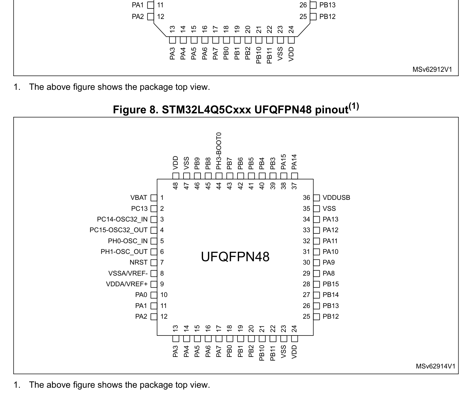
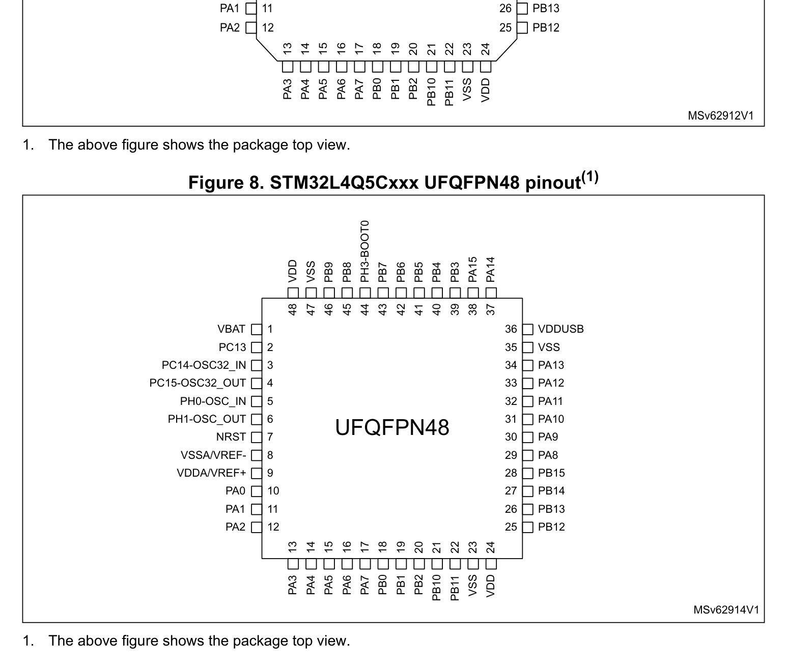
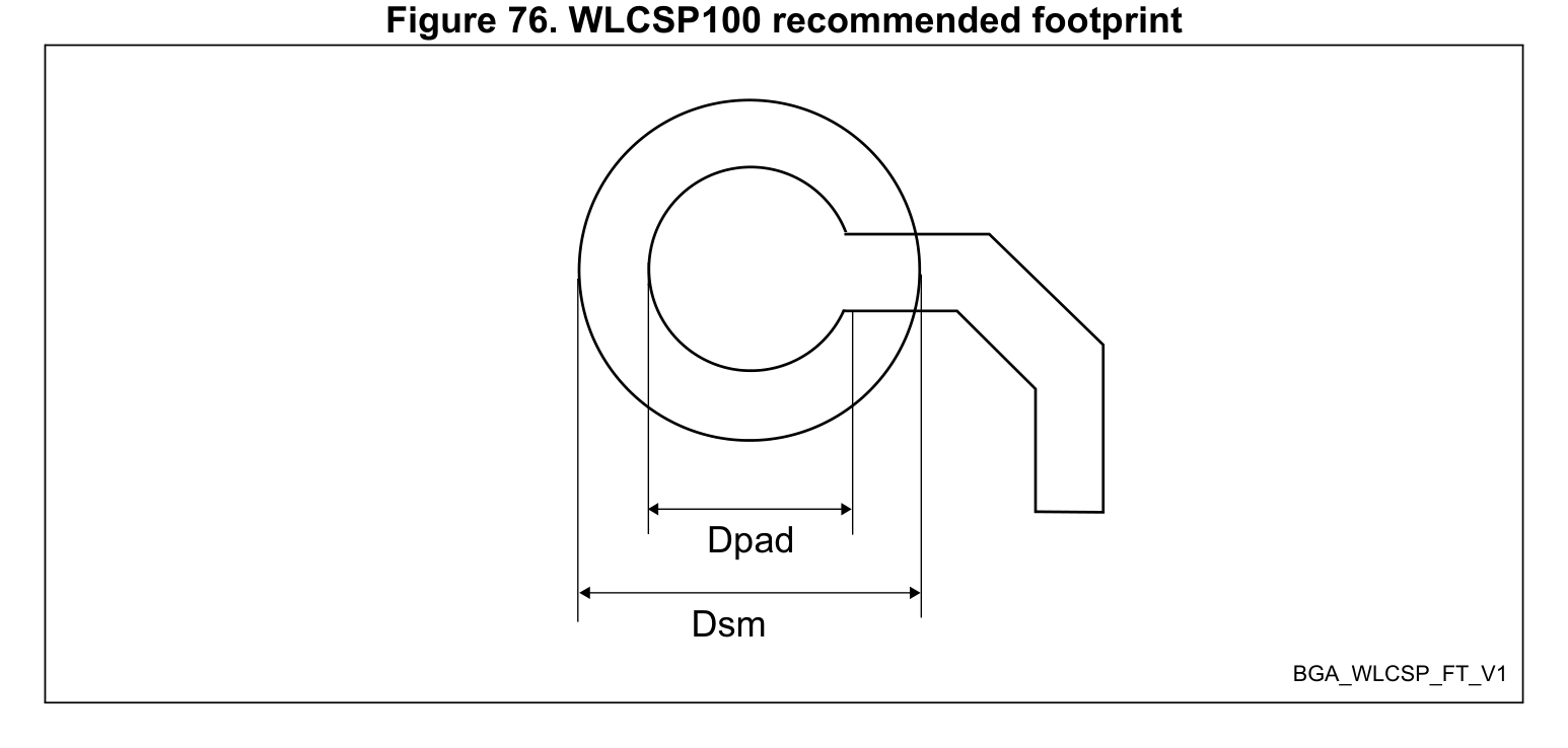
UFQFPN-48(7x7) · 49P
IPC-7351B
49P7.0×7.0×0.60mmP=0.5mm
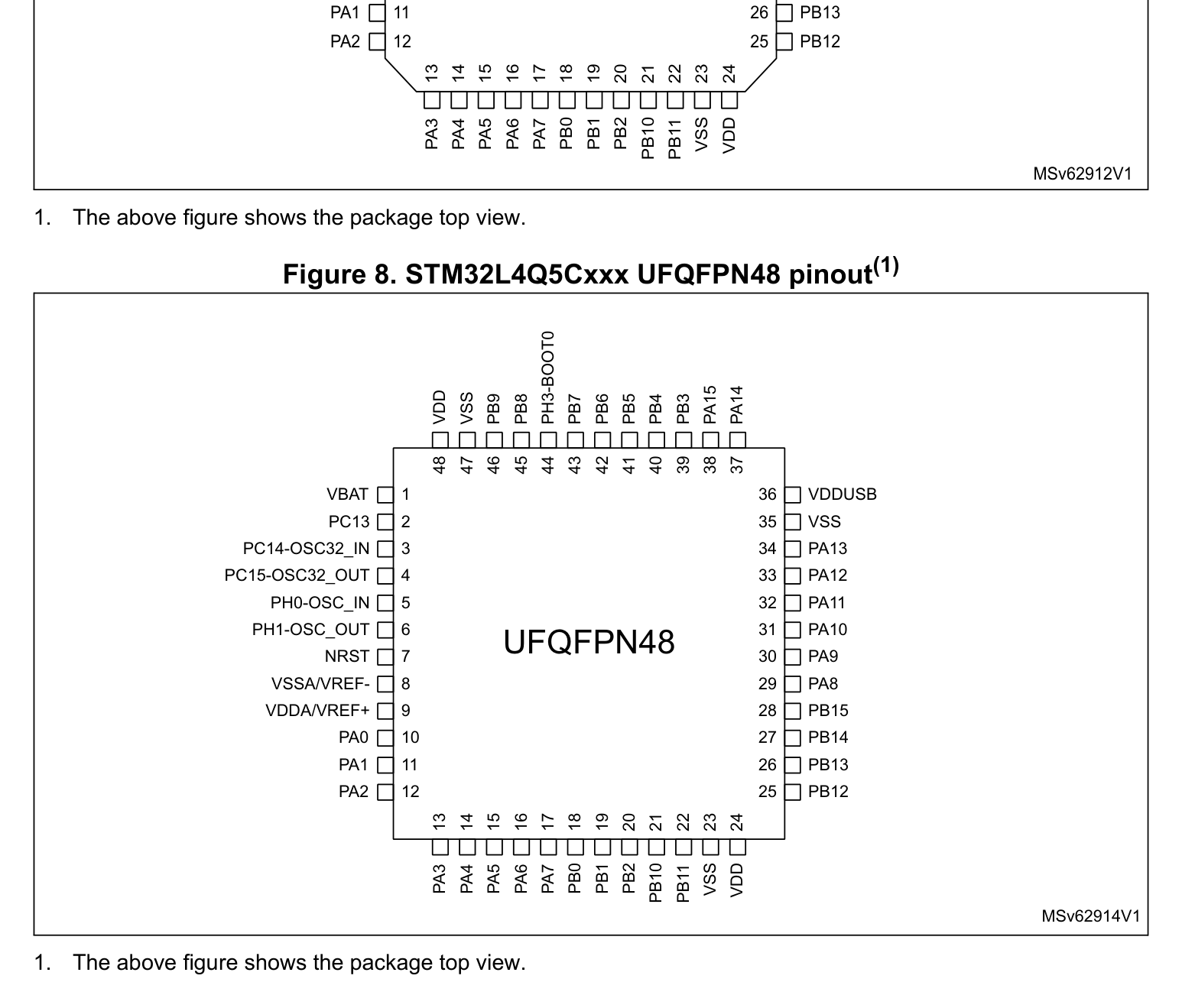
STM32L4Q5AGI / STM32L4Q5CGU / STM32L4Q5QGI (UFQFPN-48(7x7))
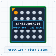
| Pin | Symbol | Typ | Funktionsbeschreibung (DE) |
|---|---|---|---|
| A1 | PI10 | I/O | Multiplex-I/O- & Peripherie-Pin PI10 (General) |
| A2 | PH2 | I/O | Multiplex-I/O- & Peripherie-Pin PH2 (General) |
| A3 | VDD | Power | Versorgungsspannungseingang (VDD — 3.3V VDD (Max 4.0V)) |
| A4 | PE0 | I/O | Multiplex-I/O- & Peripherie-Pin PE0 (General) |
| A5 | PB4 (NJTRST) | I/O | Multiplex-I/O- & Peripherie-Pin PB4 (NJTRST) (UART, SPI, I2C, SWD/JTAG) |
| A6 | PB3 (JTDO/TRAC ESWO) | I/O | Multiplex-I/O- & Peripherie-Pin PB3 (JTDO/TRAC ESWO) (UART, SPI, PWM, SWD/JTAG) |
| A7 | VSS | GND | Masseanschluss (VSS) |
| A8 | VDD | Power | Versorgungsspannungseingang (VDD — 3.3V VDD (Max 4.0V)) |
| A9 | PA15(JTDI) | I/O | Multiplex-I/O- & Peripherie-Pin PA15(JTDI) (UART, SPI, SWD/JTAG) |
| A10 | PA14 (JTCK/SWCL K) | I/O | Multiplex-I/O- & Peripherie-Pin PA14 (JTCK/SWCL K) (I2C, SWD/JTAG) |
| A11 | PA13 (JTMS/SWDI O) | I/O | Multiplex-I/O- & Peripherie-Pin PA13 (JTMS/SWDI O) (SWD/JTAG) |
| A12 | PI0 | I/O | Multiplex-I/O- & Peripherie-Pin PI0 (SPI, PWM) |
| A13 | PH14 | I/O | Multiplex-I/O- & Peripherie-Pin PH14 (PWM) |
| B1 | PI9 | I/O | Multiplex-I/O- & Peripherie-Pin PI9 (CAN) |
| B2 | PI7 | I/O | Multiplex-I/O- & Peripherie-Pin PI7 (PWM) |
| B3 | VSS | GND | Masseanschluss (VSS) |
| B4 | PE1 | I/O | Multiplex-I/O- & Peripherie-Pin PE1 (General) |
| B5 | PB5 | I/O | Multiplex-I/O- & Peripherie-Pin PB5 (UART, SPI, I2C) |
| B6 | VDDIO2 | Power | Versorgungsspannungseingang (VDDIO2 — 3.3V VDD (Max 4.0V)) |
| B7 | PG9 | I/O | Multiplex-I/O- & Peripherie-Pin PG9 (SPI) |
| B8 | PD0 | I/O | Multiplex-I/O- & Peripherie-Pin PD0 (SPI) |
| B9 | PI6 | I/O | Multiplex-I/O- & Peripherie-Pin PI6 (PWM) |
| B10 | PI2 | I/O | Multiplex-I/O- & Peripherie-Pin PI2 (PWM) |
| B11 | PI1 | I/O | Multiplex-I/O- & Peripherie-Pin PI1 (SPI) |
| B12 | PH15 | I/O | Multiplex-I/O- & Peripherie-Pin PH15 (PWM) |
| B13 | PH12 | I/O | Multiplex-I/O- & Peripherie-Pin PH12 (PWM) |
| C1 | VDD | Power | Versorgungsspannungseingang (VDD — 3.3V VDD (Max 4.0V)) |
| C2 | VSS | GND | Masseanschluss (VSS) |
| C3 | PI11 | I/O | Multiplex-I/O- & Peripherie-Pin PI11 (General) |
| C4 | PB8 | I/O | Multiplex-I/O- & Peripherie-Pin PB8 (I2C, PWM) |
| C5 | PB6 | I/O | Multiplex-I/O- & Peripherie-Pin PB6 (I2C) |
| C6 | PG15 | I/O | Multiplex-I/O- & Peripherie-Pin PG15 (General) |
| C7 | PD4 | I/O | Multiplex-I/O- & Peripherie-Pin PD4 (UART, SPI) |
| C8 | PD1 | I/O | Multiplex-I/O- & Peripherie-Pin PD1 (SPI) |
| C9 | PH13 | I/O | Multiplex-I/O- & Peripherie-Pin PH13 (PWM) |
| C10 | PI3 | I/O | Multiplex-I/O- & Peripherie-Pin PI3 (General) |
| C11 | PI8 | I/O | Multiplex-I/O- & Peripherie-Pin PI8 (General) |
| C12 | VSS | GND | Masseanschluss (VSS) |
| C13 | VDD | Power | Versorgungsspannungseingang (VDD — 3.3V VDD (Max 4.0V)) |
| D1 | PE4 | I/O | Multiplex-I/O- & Peripherie-Pin PE4 (General) |
| D2 | PE3 | I/O | Multiplex-I/O- & Peripherie-Pin PE3 (General) |
| D3 | PE2 | I/O | Multiplex-I/O- & Peripherie-Pin PE2 (General) |
| D4 | PB9 | I/O | Multiplex-I/O- & Peripherie-Pin PB9 (SPI) |
| D5 | PB7 | I/O | Multiplex-I/O- & Peripherie-Pin PB7 (UART, I2C) |
| D6 | PG10 | I/O | Multiplex-I/O- & Peripherie-Pin PG10 (SPI) |
| D7 | PD5 | I/O | Multiplex-I/O- & Peripherie-Pin PD5 (UART) |
| D8 | PD2 | I/O | Multiplex-I/O- & Peripherie-Pin PD2 (UART) |
| D9 | PC10 | I/O | Multiplex-I/O- & Peripherie-Pin PC10 (UART, SPI) |
| D10 | PI4 | I/O | Multiplex-I/O- & Peripherie-Pin PI4 (General) |
| D11 | PH9 | I/O | Multiplex-I/O- & Peripherie-Pin PH9 (I2C) |
| D12 | PH7 | I/O | Multiplex-I/O- & Peripherie-Pin PH7 (I2C) |
| D13 | PA12 | I/O | Multiplex-I/O- & Peripherie-Pin PA12 (UART, CAN) |
| E1 | PC13 | I/O | Multiplex-I/O- & Peripherie-Pin PC13 (RTC/CLK) |
| E2 | VBAT | Power | Versorgungsspannungseingang (VBAT — 3.3V VDD (Max 4.0V)) |
| E3 | PE6 | I/O | Multiplex-I/O- & Peripherie-Pin PE6 (I2C, RTC/CLK) |
| E4 | PE5 | I/O | Multiplex-I/O- & Peripherie-Pin PE5 (SPI) |
| E5 | PH3BOOT0 - | I/O | Multiplex-I/O- & Peripherie-Pin PH3BOOT0 - (General) |
| E6 | PG11 | I/O | Multiplex-I/O- & Peripherie-Pin PG11 (UART, SPI) |
| E7 | PD6 | I/O | Multiplex-I/O- & Peripherie-Pin PD6 (UART, SPI, I2C) |
| E8 | PD3 | I/O | Multiplex-I/O- & Peripherie-Pin PD3 (UART, SPI) |
| E9 | PC11 | I/O | Multiplex-I/O- & Peripherie-Pin PC11 (UART, SPI) |
| E10 | PI5 | I/O | Multiplex-I/O- & Peripherie-Pin PI5 (PWM) |
| E11 | PH6 | I/O | Multiplex-I/O- & Peripherie-Pin PH6 (I2C) |
| E12 | VDDUSB | Power | Versorgungsspannungseingang (VDDUSB — 3.3V VDD (Max 4.0V)) |
| E13 | PA11 | I/O | Multiplex-I/O- & Peripherie-Pin PA11 (UART, SPI, PWM, CAN) |
| F1 | PC14 - OSC32_IN (PC14) | I/O | Multiplex-I/O- & Peripherie-Pin PC14 - OSC32_IN (PC14) (RTC/CLK) |
| F2 | VSS | GND | Masseanschluss (VSS) |
| F3 | PF2 | I/O | Multiplex-I/O- & Peripherie-Pin PF2 (I2C) |
| F4 | PF1 | I/O | Multiplex-I/O- & Peripherie-Pin PF1 (I2C) |
| F5 | PF0 | I/O | Multiplex-I/O- & Peripherie-Pin PF0 (I2C) |
| F6 | PG12 | I/O | Multiplex-I/O- & Peripherie-Pin PG12 (UART, SPI, I2C) |
| F7 | PD7 | I/O | Multiplex-I/O- & Peripherie-Pin PD7 (UART) |
| F8 | PC12 | I/O | Multiplex-I/O- & Peripherie-Pin PC12 (UART, SPI) |
| F9 | PA10 | I/O | Multiplex-I/O- & Peripherie-Pin PA10 (UART, PWM) |
| F10 | PA9 | I/O | Multiplex-I/O- & Peripherie-Pin PA9 (UART, PWM) |
| F11 | PC6 | I/O | Multiplex-I/O- & Peripherie-Pin PC6 (PWM) |
| F12 | VDDIO2 | Power | Versorgungsspannungseingang (VDDIO2 — 3.3V VDD (Max 4.0V)) |
| F13 | VSS | GND | Masseanschluss (VSS) |
| G1 | IOG1 | I/O | General Purpose Digital I/O Pin IOG1 |
| G2 | VDD | Power | Versorgungsspannungseingang (VDD — 3.3V VDD (Max 4.0V)) |
| G3 | PF3 | I/O | Multiplex-I/O- & Peripherie-Pin PF3 (General) |
| G4 | PF4 | I/O | Multiplex-I/O- & Peripherie-Pin PF4 (General) |
| G5 | PF5 | I/O | Multiplex-I/O- & Peripherie-Pin PF5 (General) |
| G6 | PG14 | I/O | Multiplex-I/O- & Peripherie-Pin PG14 (I2C) |
| G7 | PG13 | I/O | Multiplex-I/O- & Peripherie-Pin PG13 (I2C) |
| G8 | PA8 | I/O | Multiplex-I/O- & Peripherie-Pin PA8 (SPI, RTC/CLK) |
| G9 | PC9 | I/O | Multiplex-I/O- & Peripherie-Pin PC9 (I2C, PWM) |
| G10 | PC8 | I/O | Multiplex-I/O- & Peripherie-Pin PC8 (PWM) |
| G11 | PG6 | I/O | Multiplex-I/O- & Peripherie-Pin PG6 (UART, I2C) |
| G12 | PC7 | I/O | Multiplex-I/O- & Peripherie-Pin PC7 (PWM) |
| G13 | VDD_15 | Power | Versorgungsspannungseingang (VDD_15 — 3.3V VDD (Max 4.0V)) |
| H1 | PH0OSC IN -_ (PH0) | I/O | Multiplex-I/O- & Peripherie-Pin PH0OSC IN -_ (PH0) (RTC/CLK) |
| H2 | VSS | GND | Masseanschluss (VSS) |
| H3 | NRST | I | Systemfreigabe & Hardware-Reset (NRST) |
| H4 | PF10 | I/O | Multiplex-I/O- & Peripherie-Pin PF10 (General) |
| H5 | PC4 | I/O | Multiplex-I/O- & Peripherie-Pin PC4 (UART, ADC) |
| H6 | PG1 | I/O | Multiplex-I/O- & Peripherie-Pin PG1 (General) |
| H7 | PE10 | I/O | Multiplex-I/O- & Peripherie-Pin PE10 (General) |
| H8 | PB11 | I/O | Multiplex-I/O- & Peripherie-Pin PB11 (I2C, PWM) |
| H9 | PG8 | I/O | Multiplex-I/O- & Peripherie-Pin PG8 (I2C) |
| H10 | PG7 | I/O | Multiplex-I/O- & Peripherie-Pin PG7 (General) |
| H11 | PD15 | I/O | Multiplex-I/O- & Peripherie-Pin PD15 (PWM) |
| H12 | VSS | GND | Masseanschluss (VSS) |
| H13 | VDD | Power | Versorgungsspannungseingang (VDD — 3.3V VDD (Max 4.0V)) |
| J1 | PH1 - OSC_OUT (PH1) | I/O | Multiplex-I/O- & Peripherie-Pin PH1 - OSC_OUT (PH1) (RTC/CLK) |
| J2 | PC0 | I/O | Multiplex-I/O- & Peripherie-Pin PC0 (ADC) |
| J3 | PC1 | I/O | Multiplex-I/O- & Peripherie-Pin PC1 (SPI, I2C, ADC) |
| J4 | PC2 | I/O | Multiplex-I/O- & Peripherie-Pin PC2 (ADC) |
| J5 | PC5 | I/O | Multiplex-I/O- & Peripherie-Pin PC5 (UART, ADC) |
| J6 | PG0 | I/O | Multiplex-I/O- & Peripherie-Pin PG0 (General) |
| J7 | PE9 | I/O | Multiplex-I/O- & Peripherie-Pin PE9 (PWM) |
| J8 | PE15 | I/O | Multiplex-I/O- & Peripherie-Pin PE15 (General) |
| J9 | PG5 | I/O | Multiplex-I/O- & Peripherie-Pin PG5 (SPI) |
| J10 | PG4 | I/O | Multiplex-I/O- & Peripherie-Pin PG4 (SPI) |
| J11 | PG3 | I/O | Multiplex-I/O- & Peripherie-Pin PG3 (SPI) |
| J12 | PG2 | I/O | Multiplex-I/O- & Peripherie-Pin PG2 (SPI) |
| J13 | PD10 | I/O | Multiplex-I/O- & Peripherie-Pin PD10 (UART, SPI) |
| K1 | PC3 | I/O | Multiplex-I/O- & Peripherie-Pin PC3 (SPI, ADC) |
| K2 | VSSA/VREF - | GND | Masseanschluss (VSSA/VREF -) |
| K3 | PA0 | I/O | Multiplex-I/O- & Peripherie-Pin PA0 (UART, ADC, PWM, RTC/CLK) |
| K4 | PA5 | I/O | Multiplex-I/O- & Peripherie-Pin PA5 (SPI, ADC, DAC, PWM) |
| K5 | PB0 | I/O | Multiplex-I/O- & Peripherie-Pin PB0 (UART, ADC, PWM) |
| K6 | PF15 | I/O | Multiplex-I/O- & Peripherie-Pin PF15 (I2C) |
| K7 | PE8 | I/O | Multiplex-I/O- & Peripherie-Pin PE8 (PWM) |
| K8 | PE14 | I/O | Multiplex-I/O- & Peripherie-Pin PE14 (SPI, PWM) |
| K9 | PH4 | I/O | Multiplex-I/O- & Peripherie-Pin PH4 (I2C) |
| K10 | PD14 | I/O | Multiplex-I/O- & Peripherie-Pin PD14 (PWM) |
| K11 | PD12 | I/O | Multiplex-I/O- & Peripherie-Pin PD12 (UART, PWM) |
| K12 | PD11 | I/O | Multiplex-I/O- & Peripherie-Pin PD11 (UART, I2C) |
| K13 | PD13 | I/O | Multiplex-I/O- & Peripherie-Pin PD13 (PWM) |
| L1 | VREF+ | Analog | Multiplex-I/O- & Peripherie-Pin VREF+ (General) |
| L2 | VDDA | Power | Versorgungsspannungseingang (VDDA — 3.3V VDD (Max 4.0V)) |
| L3 | PA4 | I/O | Multiplex-I/O- & Peripherie-Pin PA4 (UART, SPI, ADC, DAC) |
| L4 | PA7 | I/O | Multiplex-I/O- & Peripherie-Pin PA7 (SPI, ADC, PWM) |
| L5 | PB1 | I/O | Multiplex-I/O- & Peripherie-Pin PB1 (UART, ADC, PWM) |
| L6 | PF14 | I/O | Multiplex-I/O- & Peripherie-Pin PF14 (I2C) |
| L7 | PE7 | I/O | Multiplex-I/O- & Peripherie-Pin PE7 (General) |
| L8 | PE13 | I/O | Multiplex-I/O- & Peripherie-Pin PE13 (PWM) |
| L9 | PH5 | I/O | Multiplex-I/O- & Peripherie-Pin PH5 (I2C) |
| L10 | PD9 | I/O | Multiplex-I/O- & Peripherie-Pin PD9 (UART) |
| L11 | PD8 | I/O | Multiplex-I/O- & Peripherie-Pin PD8 (UART) |
| L12 | VDD | Power | Versorgungsspannungseingang (VDD — 3.3V VDD (Max 4.0V)) |
| L13 | VSS | GND | Masseanschluss (VSS) |
| M1 | OPAMP1_VI NM | I/O | Multiplex-I/O- & Peripherie-Pin OPAMP1_VI NM (General) |
| M2 | PA3 | I/O | Multiplex-I/O- & Peripherie-Pin PA3 (ADC, PWM) |
| M3 | VSS | GND | Masseanschluss (VSS) |
| M4 | PA6 | I/O | Multiplex-I/O- & Peripherie-Pin PA6 (UART, SPI, ADC) |
| M5 | PF11 | I/O | Multiplex-I/O- & Peripherie-Pin PF11 (General) |
| M6 | PF13 | I/O | Multiplex-I/O- & Peripherie-Pin PF13 (I2C) |
| M7 | VSS | GND | Masseanschluss (VSS) |
| M8 | PE12 | I/O | Multiplex-I/O- & Peripherie-Pin PE12 (PWM) |
| M9 | PH10 | I/O | Multiplex-I/O- & Peripherie-Pin PH10 (PWM) |
| M10 | PH11 | I/O | Multiplex-I/O- & Peripherie-Pin PH11 (PWM) |
| M11 | VSS | GND | Masseanschluss (VSS) |
| M12 | PB15 | I/O | Multiplex-I/O- & Peripherie-Pin PB15 (PWM, RTC/CLK) |
| M13 | PB14 | I/O | Multiplex-I/O- & Peripherie-Pin PB14 (UART, I2C, PWM) |
| N1 | PA2 | I/O | Multiplex-I/O- & Peripherie-Pin PA2 (UART, ADC, PWM) |
| N2 | PA1 | I/O | Multiplex-I/O- & Peripherie-Pin PA1 (UART, I2C, ADC, PWM) |
| N3 | VDD | Power | Versorgungsspannungseingang (VDD — 3.3V VDD (Max 4.0V)) |
| N4 | OPAMP2_VI NM | I/O | Multiplex-I/O- & Peripherie-Pin OPAMP2_VI NM (General) |
| N5 | PB2 | I/O | Multiplex-I/O- & Peripherie-Pin PB2 (I2C, RTC/CLK) |
| N6 | PF12 | I/O | Multiplex-I/O- & Peripherie-Pin PF12 (General) |
| N7 | VDD | Power | Versorgungsspannungseingang (VDD — 3.3V VDD (Max 4.0V)) |
| N8 | PE11 | I/O | Multiplex-I/O- & Peripherie-Pin PE11 (General) |
| N9 | PB10 | I/O | Multiplex-I/O- & Peripherie-Pin PB10 (UART, SPI, I2C, PWM) |
| N10 | PH8 | I/O | Multiplex-I/O- & Peripherie-Pin PH8 (I2C) |
| N11 | VDD | Power | Versorgungsspannungseingang (VDD — 3.3V VDD (Max 4.0V)) |
| N12 | PB12 | I/O | Multiplex-I/O- & Peripherie-Pin PB12 (UART, SPI) |
| N13 | PB13 | I/O | Multiplex-I/O- & Peripherie-Pin PB13 (UART, SPI, PWM) |
STM32L4Q5AGI / STM32L4Q5CGU / STM32L4Q5QGI (UFQFPN-48(7x7))
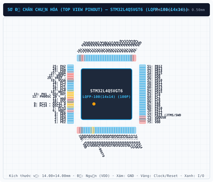
STM32L4Q5AGI / STM32L4Q5CGU / STM32L4Q5QGI (LQFP-100(14x14))
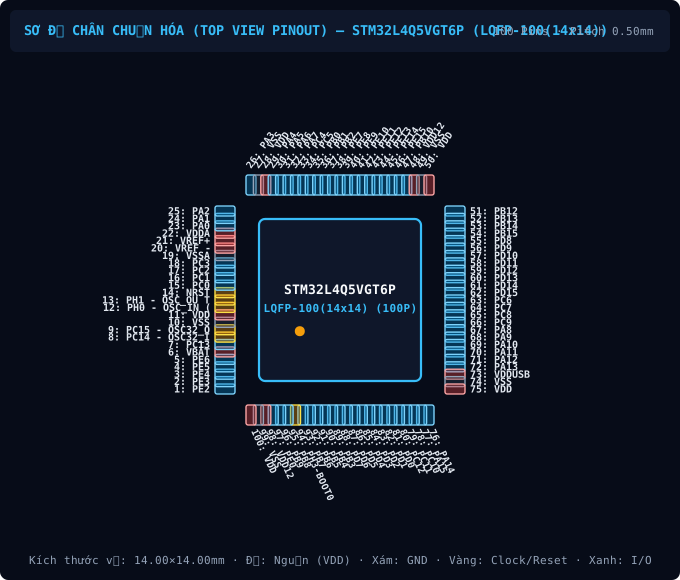
STM32L4Q5AGI / STM32L4Q5CGU / STM32L4Q5QGI (LQFP-100(14x14))
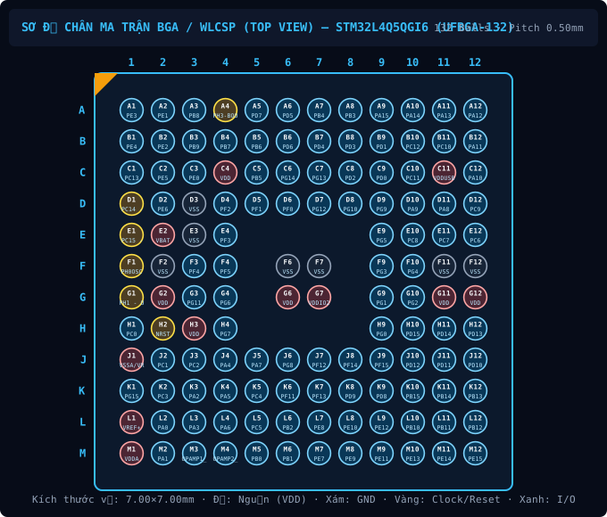
STM32L4Q5AGI / STM32L4Q5CGU / STM32L4Q5QGI (UFBGA-132)
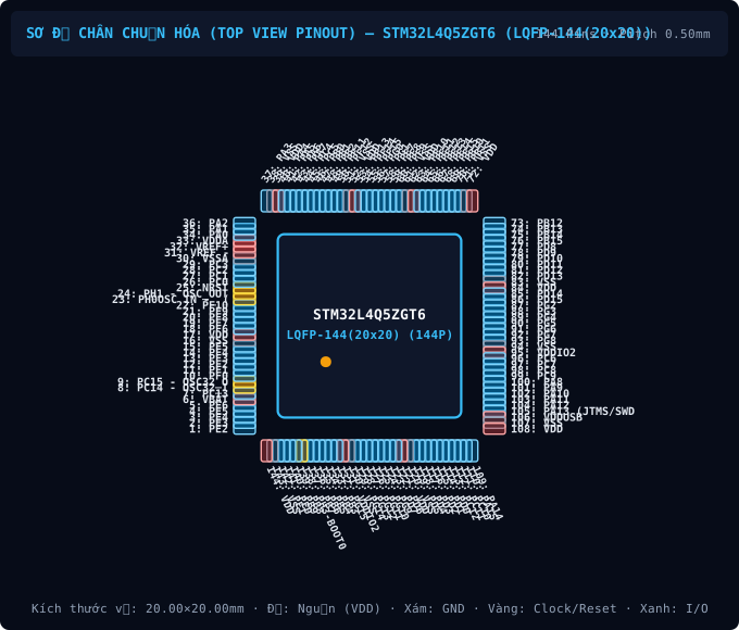
STM32L4Q5AGI / STM32L4Q5CGU / STM32L4Q5QGI (LQFP-144(20x20))
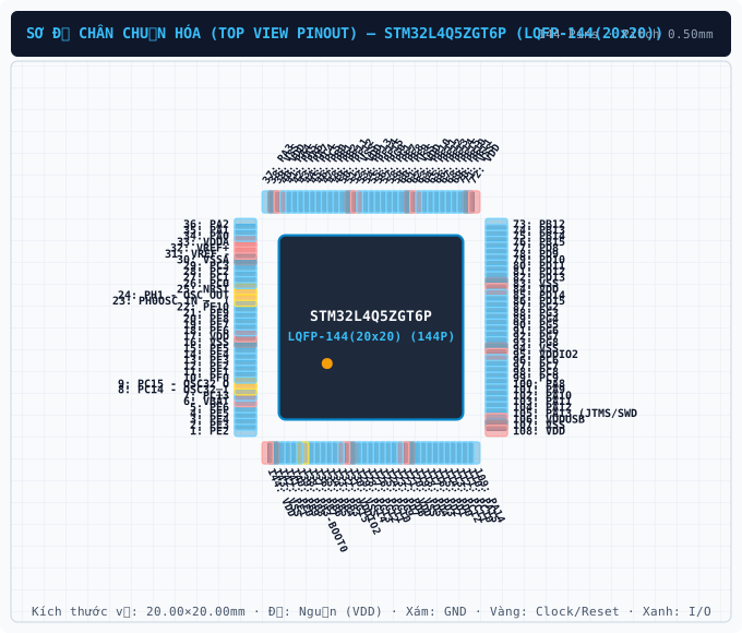
STM32L4Q5AGI / STM32L4Q5CGU / STM32L4Q5QGI (LQFP-144(20x20))
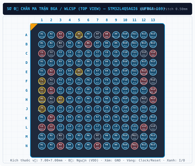
STM32L4Q5AGI / STM32L4Q5CGU / STM32L4Q5QGI (UFBGA-169)
| Bauteilbezeichner / Ersatz-MPN | Wert / Gehäuse | Funktion & PCB-Layout-Regel |
|---|---|---|
| N/A BOM | Per application circuit UFBGA-169 | Leiterbahnbreiten für Nennstrom dimensionieren und IPC-2221 Isolationsabstände einhalten. |
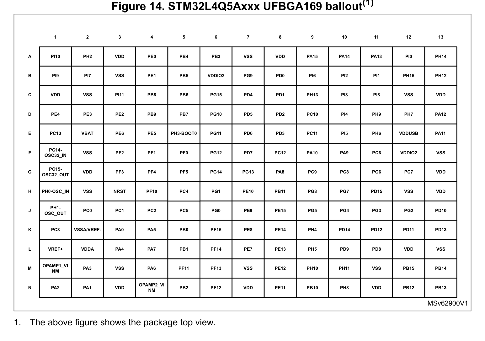
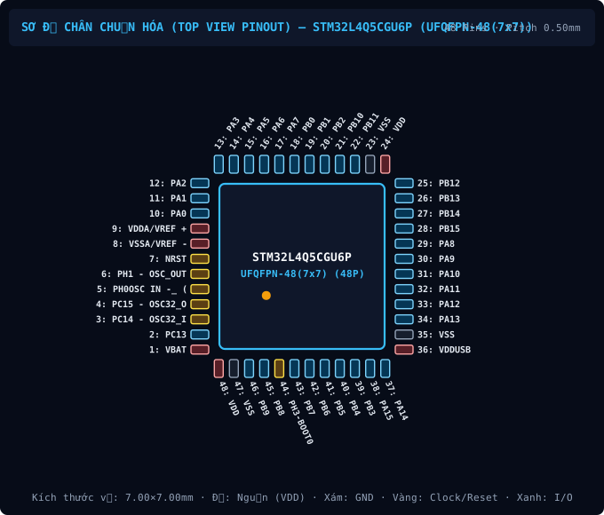
Das Bauteil STM32L4Q5AGI6 von ST im UFBGA-169-Gehäuse besitzt 169 Pins mit einem Rastermaß (Pitch) von 0.50 mm und einem Betriebsspannungsbereich VCC von 1.71 V to 3.6 V. Wichtige Pins: A1 (PI10: Multiplex-I/O- & Peripherie-Pin PI10 (General)), A2 (PH2: Multiplex-I/O- & Peripherie-Pin PH2 (General)), A3 (VDD: Versorgungsspannungseingang (VDD — 3.3V VDD (Max 4.0V))), A4 (PE0: Multiplex-I/O- & Peripherie-Pin PE0 (General)), A5 (PB4 (NJTRST): Multiplex-I/O- & Peripherie-Pin PB4 (NJTRST) (UART, SPI, I2C, SWD/JTAG)), A6 (PB3 (JTDO/TRAC ESWO): Multiplex-I/O- & Peripherie-Pin PB3 (JTDO/TRAC ESWO) (UART, SPI, PWM, SWD/JTAG)).
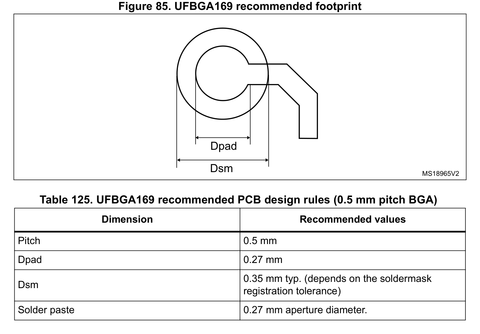
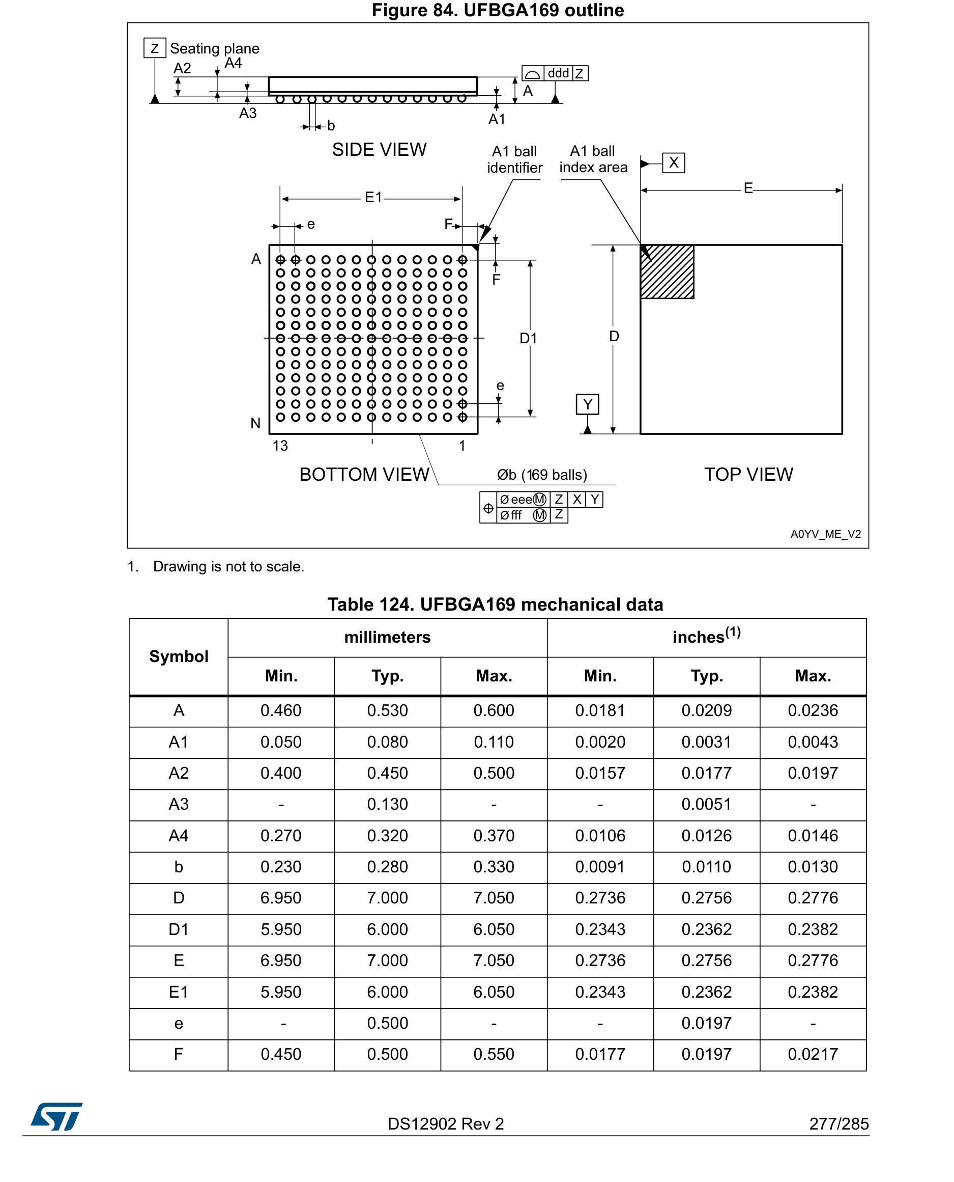
Gemäß Datenblatt und IPC-7351B (Density Level B Nominal) betragen die Gehäusemaße des STM32L4Q5AGI6 (UFBGA-169) 7.00 × 7.00 mm bei einem Pitch e = 0.50 mm und 169 Kupfer-Pads.
Auf dieser Seite können Sie das vollständig verifizierte CAD-Bibliothekspaket für STM32L4Q5AGI6 (ST, UFBGA-169) unter der Open-Hardware-Lizenz CERN-OHL-P-2.0 kostenlos herunterladen: KiCad 8 Footprint (.kicad_mod), Schaltplansymbol (.kicad_sym), Fusion 360 / Eagle (.lbr) und 3D STEP AP214 / WebGL GLB.
| Pin-Nr. | Signalname | Elektrischer Typ | Funktionsbeschreibung & Schaltungshinweise |
|---|---|---|---|
| A1 | PI10 | Digital_IO | Signalanschluss PI10 (Richtung: I/O, Spannungsbereich: 3.3V VDD (5V-Tolerant FT)). Alternative Multiplex-Funktionen: PI10. Unterstützte Bus-Schnittstellen: General. |
| A2 | PH2 | Digital_IO | Signalanschluss PH2 (Richtung: I/O, Spannungsbereich: 3.3V VDD (5V-Tolerant FT)). Alternative Multiplex-Funktionen: PH2. Unterstützte Bus-Schnittstellen: General. |
| A3 | VDD | Power_In | Positiver Versorgungseingang (VDD) im Spannungsbereich 3.3V VDD (Max 4.0V) (Max. 4.0V). |
| A4 | PE0 | Digital_IO | Signalanschluss PE0 (Richtung: I/O, Spannungsbereich: 3.3V VDD (5V-Tolerant FT)). Alternative Multiplex-Funktionen: PE0. Unterstützte Bus-Schnittstellen: General. |
| A5 | PB4 (NJTRST) | Digital_IO | Signalanschluss PB4 (NJTRST) (Richtung: I/O, Spannungsbereich: 3.3V VDD (5V-Tolerant FT)). Alternative Multiplex-Funktionen: SPI3_MISO. Unterstützte Bus-Schnittstellen: UART, SPI, I2C, SWD/JTAG. |
| A6 | PB3 (JTDO/TRAC ESWO) | Digital_IO | Signalanschluss PB3 (JTDO/TRAC ESWO) (Richtung: I/O, Spannungsbereich: 3.3V VDD (5V-Tolerant FT)). Alternative Multiplex-Funktionen: SPI1_SCKSPI3SCK. Unterstützte Bus-Schnittstellen: UART, SPI, PWM, SWD/JTAG. |
| A7 | VSS | GND | Elektrischer 0V-Masserückführungsanschluss (VSS) für Kernlogik, I/O-Treiber und Analogblöcke. |
| A8 | VDD | Power_In | Positiver Versorgungseingang (VDD) im Spannungsbereich 3.3V VDD (Max 4.0V) (Max. 4.0V). |
| A9 | PA15(JTDI) | Digital_IO | Signalanschluss PA15(JTDI) (Richtung: I/O, Spannungsbereich: 3.3V VDD (5V-Tolerant FT)). Alternative Multiplex-Funktionen: SPI1_NSSSPI3NSS. Unterstützte Bus-Schnittstellen: UART, SPI, SWD/JTAG. |
| A10 | PA14 (JTCK/SWCL K) | Digital_IO | Signalanschluss PA14 (JTCK/SWCL K) (Richtung: I/O, Spannungsbereich: 3.3V VDD (5V-Tolerant FT)). Alternative Multiplex-Funktionen: I2C4_SMBA. Unterstützte Bus-Schnittstellen: I2C, SWD/JTAG. |
| A11 | PA13 (JTMS/SWDI O) | Digital_IO | Signalanschluss PA13 (JTMS/SWDI O) (Richtung: I/O, Spannungsbereich: 3.3V VDD (5V-Tolerant FT)). Alternative Multiplex-Funktionen: PA13 (JTMS/SWDI O). Unterstützte Bus-Schnittstellen: SWD/JTAG. |
| A12 | PI0 | Digital_IO | Signalanschluss PI0 (Richtung: I/O, Spannungsbereich: 3.3V VDD (5V-Tolerant FT)). Alternative Multiplex-Funktionen: SPI2_NSS. Unterstützte Bus-Schnittstellen: SPI, PWM. |
| A13 | PH14 | Digital_IO | Signalanschluss PH14 (Richtung: I/O, Spannungsbereich: 3.3V VDD (5V-Tolerant FT)). Alternative Multiplex-Funktionen: PH14. Unterstützte Bus-Schnittstellen: PWM. |
| B1 | PI9 | Digital_IO | Signalanschluss PI9 (Richtung: I/O, Spannungsbereich: 3.3V VDD (5V-Tolerant FT)). Alternative Multiplex-Funktionen: PI9. Unterstützte Bus-Schnittstellen: CAN. |
| B2 | PI7 | Digital_IO | Signalanschluss PI7 (Richtung: I/O, Spannungsbereich: 3.3V VDD (5V-Tolerant FT)). Alternative Multiplex-Funktionen: PI7. Unterstützte Bus-Schnittstellen: PWM. |
| B3 | VSS | GND | Elektrischer 0V-Masserückführungsanschluss (VSS) für Kernlogik, I/O-Treiber und Analogblöcke. |
| B4 | PE1 | Digital_IO | Signalanschluss PE1 (Richtung: I/O, Spannungsbereich: 3.3V VDD (5V-Tolerant FT)). Alternative Multiplex-Funktionen: PE1. Unterstützte Bus-Schnittstellen: General. |
| B5 | PB5 | Digital_IO | Signalanschluss PB5 (Richtung: I/O, Spannungsbereich: 3.3V VDD (5V-Tolerant FT)). Alternative Multiplex-Funktionen: SPI3_MOSIUSART1CK. Unterstützte Bus-Schnittstellen: UART, SPI, I2C. |
| B6 | VDDIO2 | Power_In | Positiver Versorgungseingang (VDDIO2) im Spannungsbereich 3.3V VDD (Max 4.0V) (Max. 4.0V). |
| B7 | PG9 | Digital_IO | Signalanschluss PG9 (Richtung: I/O, Spannungsbereich: 3.3V VDD (5V-Tolerant FT)). Alternative Multiplex-Funktionen: SPI3_SCKUSART1TX. Unterstützte Bus-Schnittstellen: SPI. |
| B8 | PD0 | Digital_IO | Signalanschluss PD0 (Richtung: I/O, Spannungsbereich: 3.3V VDD (5V-Tolerant FT)). Alternative Multiplex-Funktionen: SPI2_NSSCAN1RX. Unterstützte Bus-Schnittstellen: SPI. |
| B9 | PI6 | Digital_IO | Signalanschluss PI6 (Richtung: I/O, Spannungsbereich: 3.3V VDD (5V-Tolerant FT)). Alternative Multiplex-Funktionen: PI6. Unterstützte Bus-Schnittstellen: PWM. |
| B10 | PI2 | Digital_IO | Signalanschluss PI2 (Richtung: I/O, Spannungsbereich: 3.3V VDD (5V-Tolerant FT)). Alternative Multiplex-Funktionen: PI2. Unterstützte Bus-Schnittstellen: PWM. |
| B11 | PI1 | Digital_IO | Signalanschluss PI1 (Richtung: I/O, Spannungsbereich: 3.3V VDD (5V-Tolerant FT)). Alternative Multiplex-Funktionen: SPI2_SCK. Unterstützte Bus-Schnittstellen: SPI. |
| B12 | PH15 | Digital_IO | Signalanschluss PH15 (Richtung: I/O, Spannungsbereich: 3.3V VDD (5V-Tolerant FT)). Alternative Multiplex-Funktionen: PH15. Unterstützte Bus-Schnittstellen: PWM. |
| B13 | PH12 | Digital_IO | Signalanschluss PH12 (Richtung: I/O, Spannungsbereich: 3.3V VDD (5V-Tolerant FT)). Alternative Multiplex-Funktionen: PH12. Unterstützte Bus-Schnittstellen: PWM. |
| C1 | VDD | Power_In | Positiver Versorgungseingang (VDD) im Spannungsbereich 3.3V VDD (Max 4.0V) (Max. 4.0V). |
| C2 | VSS | GND | Elektrischer 0V-Masserückführungsanschluss (VSS) für Kernlogik, I/O-Treiber und Analogblöcke. |
| C3 | PI11 | Digital_IO | Signalanschluss PI11 (Richtung: I/O, Spannungsbereich: 3.3V VDD (5V-Tolerant FT)). Alternative Multiplex-Funktionen: PI11. Unterstützte Bus-Schnittstellen: General. |
| C4 | PB8 | Digital_IO | Signalanschluss PB8 (Richtung: I/O, Spannungsbereich: 3.3V VDD (5V-Tolerant FT)). Alternative Multiplex-Funktionen: I2C1_SCL. Unterstützte Bus-Schnittstellen: I2C, PWM. |
| C5 | PB6 | Digital_IO | Signalanschluss PB6 (Richtung: I/O, Spannungsbereich: 3.3V VDD (5V-Tolerant FT)). Alternative Multiplex-Funktionen: PB6. Unterstützte Bus-Schnittstellen: I2C. |
| C6 | PG15 | Digital_IO | Signalanschluss PG15 (Richtung: I/O, Spannungsbereich: 3.3V VDD (5V-Tolerant FT)). Alternative Multiplex-Funktionen: PG15. Unterstützte Bus-Schnittstellen: General. |
| C7 | PD4 | Digital_IO | Signalanschluss PD4 (Richtung: I/O, Spannungsbereich: 3.3V VDD (5V-Tolerant FT)). Alternative Multiplex-Funktionen: SPI2_MOSI. Unterstützte Bus-Schnittstellen: UART, SPI. |
| C8 | PD1 | Digital_IO | Signalanschluss PD1 (Richtung: I/O, Spannungsbereich: 3.3V VDD (5V-Tolerant FT)). Alternative Multiplex-Funktionen: SPI2_SCKCAN1TX. Unterstützte Bus-Schnittstellen: SPI. |
| C9 | PH13 | Digital_IO | Signalanschluss PH13 (Richtung: I/O, Spannungsbereich: 3.3V VDD (5V-Tolerant FT)). Alternative Multiplex-Funktionen: PH13. Unterstützte Bus-Schnittstellen: PWM. |
| C10 | PI3 | Digital_IO | Signalanschluss PI3 (Richtung: I/O, Spannungsbereich: 3.3V VDD (5V-Tolerant FT)). Alternative Multiplex-Funktionen: PI3. Unterstützte Bus-Schnittstellen: General. |
| C11 | PI8 | Digital_IO | Signalanschluss PI8 (Richtung: I/O, Spannungsbereich: 3.3V VDD (5V-Tolerant FT)). Alternative Multiplex-Funktionen: PI8. Unterstützte Bus-Schnittstellen: General. |
| C12 | VSS | GND | Elektrischer 0V-Masserückführungsanschluss (VSS) für Kernlogik, I/O-Treiber und Analogblöcke. |
| C13 | VDD | Power_In | Positiver Versorgungseingang (VDD) im Spannungsbereich 3.3V VDD (Max 4.0V) (Max. 4.0V). |
| D1 | PE4 | Digital_IO | Signalanschluss PE4 (Richtung: I/O, Spannungsbereich: 3.3V VDD (5V-Tolerant FT)). Alternative Multiplex-Funktionen: PE4. Unterstützte Bus-Schnittstellen: General. |
| D2 | PE3 | Digital_IO | Signalanschluss PE3 (Richtung: I/O, Spannungsbereich: 3.3V VDD (5V-Tolerant FT)). Alternative Multiplex-Funktionen: PE3. Unterstützte Bus-Schnittstellen: General. |
| D3 | PE2 | Digital_IO | Signalanschluss PE2 (Richtung: I/O, Spannungsbereich: 3.3V VDD (5V-Tolerant FT)). Alternative Multiplex-Funktionen: PE2. Unterstützte Bus-Schnittstellen: General. |
| D4 | PB9 | Digital_IO | Signalanschluss PB9 (Richtung: I/O, Spannungsbereich: 3.3V VDD (5V-Tolerant FT)). Alternative Multiplex-Funktionen: SPI2_NSSSDMMC2D5. Unterstützte Bus-Schnittstellen: SPI. |
| D5 | PB7 | Digital_IO | Signalanschluss PB7 (Richtung: I/O, Spannungsbereich: 3.3V VDD (5V-Tolerant FT)). Alternative Multiplex-Funktionen: PB7. Unterstützte Bus-Schnittstellen: UART, I2C. |
| D6 | PG10 | Digital_IO | Signalanschluss PG10 (Richtung: I/O, Spannungsbereich: 3.3V VDD (5V-Tolerant FT)). Alternative Multiplex-Funktionen: SPI3_MISOUSART1RX. Unterstützte Bus-Schnittstellen: SPI. |
| D7 | PD5 | Digital_IO | Signalanschluss PD5 (Richtung: I/O, Spannungsbereich: 3.3V VDD (5V-Tolerant FT)). Alternative Multiplex-Funktionen: PD5. Unterstützte Bus-Schnittstellen: UART. |
| D8 | PD2 | Digital_IO | Signalanschluss PD2 (Richtung: I/O, Spannungsbereich: 3.3V VDD (5V-Tolerant FT)). Alternative Multiplex-Funktionen: PD2. Unterstützte Bus-Schnittstellen: UART. |
| D9 | PC10 | Digital_IO | Signalanschluss PC10 (Richtung: I/O, Spannungsbereich: 3.3V VDD (5V-Tolerant FT)). Alternative Multiplex-Funktionen: SPI3_SCKUSART3TX. Unterstützte Bus-Schnittstellen: UART, SPI. |
| D10 | PI4 | Digital_IO | Signalanschluss PI4 (Richtung: I/O, Spannungsbereich: 3.3V VDD (5V-Tolerant FT)). Alternative Multiplex-Funktionen: PI4. Unterstützte Bus-Schnittstellen: General. |
| D11 | PH9 | Digital_IO | Signalanschluss PH9 (Richtung: I/O, Spannungsbereich: 3.3V VDD (5V-Tolerant FT)). Alternative Multiplex-Funktionen: I2C3_SMBA. Unterstützte Bus-Schnittstellen: I2C. |
| D12 | PH7 | Digital_IO | Signalanschluss PH7 (Richtung: I/O, Spannungsbereich: 3.3V VDD (5V-Tolerant FT)). Alternative Multiplex-Funktionen: I2C3_SCL. Unterstützte Bus-Schnittstellen: I2C. |
| D13 | PA12 | Digital_IO | Signalanschluss PA12 (Richtung: I/O, Spannungsbereich: 3.3V VDD (5V-Tolerant FT)). Alternative Multiplex-Funktionen: PA12. Unterstützte Bus-Schnittstellen: UART, CAN. |
| E1 | PC13 | Digital_IO | Signalanschluss PC13 (Richtung: I/O, Spannungsbereich: 3.3V VDD (5V-Tolerant FT)). Alternative Multiplex-Funktionen: PC13. Unterstützte Bus-Schnittstellen: RTC/CLK. |
| E2 | VBAT | Power_In | Positiver Versorgungseingang (VBAT) im Spannungsbereich 3.3V VDD (Max 4.0V) (Max. 4.0V). |
| E3 | PE6 | Digital_IO | Signalanschluss PE6 (Richtung: I/O, Spannungsbereich: 3.3V VDD (5V-Tolerant FT)). Alternative Multiplex-Funktionen: PE6. Unterstützte Bus-Schnittstellen: I2C, RTC/CLK. |
| E4 | PE5 | Digital_IO | Signalanschluss PE5 (Richtung: I/O, Spannungsbereich: 3.3V VDD (5V-Tolerant FT)). Alternative Multiplex-Funktionen: PE5. Unterstützte Bus-Schnittstellen: SPI. |
| E5 | PH3BOOT0 - | Digital_IO | Signalanschluss PH3BOOT0 - (Richtung: I/O, Spannungsbereich: 3.3V VDD (5V-Tolerant FT)). Alternative Multiplex-Funktionen: PH3BOOT0 -. Unterstützte Bus-Schnittstellen: General. |
| E6 | PG11 | Digital_IO | Signalanschluss PG11 (Richtung: I/O, Spannungsbereich: 3.3V VDD (5V-Tolerant FT)). Alternative Multiplex-Funktionen: SPI3_MOSI. Unterstützte Bus-Schnittstellen: UART, SPI. |
| E7 | PD6 | Digital_IO | Signalanschluss PD6 (Richtung: I/O, Spannungsbereich: 3.3V VDD (5V-Tolerant FT)). Alternative Multiplex-Funktionen: SPI3_MOSI. Unterstützte Bus-Schnittstellen: UART, SPI, I2C. |
| E8 | PD3 | Digital_IO | Signalanschluss PD3 (Richtung: I/O, Spannungsbereich: 3.3V VDD (5V-Tolerant FT)). Alternative Multiplex-Funktionen: SPI2_SCK, SPI2_MISO. Unterstützte Bus-Schnittstellen: UART, SPI. |
| E9 | PC11 | Digital_IO | Signalanschluss PC11 (Richtung: I/O, Spannungsbereich: 3.3V VDD (5V-Tolerant FT)). Alternative Multiplex-Funktionen: SPI3_MISOUSART3RX. Unterstützte Bus-Schnittstellen: UART, SPI. |
| E10 | PI5 | Digital_IO | Signalanschluss PI5 (Richtung: I/O, Spannungsbereich: 3.3V VDD (5V-Tolerant FT)). Alternative Multiplex-Funktionen: PI5. Unterstützte Bus-Schnittstellen: PWM. |
| E11 | PH6 | Digital_IO | Signalanschluss PH6 (Richtung: I/O, Spannungsbereich: 3.3V VDD (5V-Tolerant FT)). Alternative Multiplex-Funktionen: I2C2_SMBA. Unterstützte Bus-Schnittstellen: I2C. |
| E12 | VDDUSB | Power_In | Positiver Versorgungseingang (VDDUSB) im Spannungsbereich 3.3V VDD (Max 4.0V) (Max. 4.0V). |