AGLP060V5-CSG201 (CSP-201(8x8)) — Symbol, Footprint IPC-7351B & 3D STEP Model

AGLP060V5-CSG201

MICROCHIPID: C5582677CSP-201(8x8) · 201 Pins · Pitch 0.50mmIPC-7351B Verified5.0 (0)
SYNCHRONISIERTER 4D-CROSS-PROBE-MODUSKlicken oder berühren Sie einen Pin, um ihn zeitgleich in Symbol, Footprint und 3D hervorzuheben
1. SCHALTPLANSYMBOL
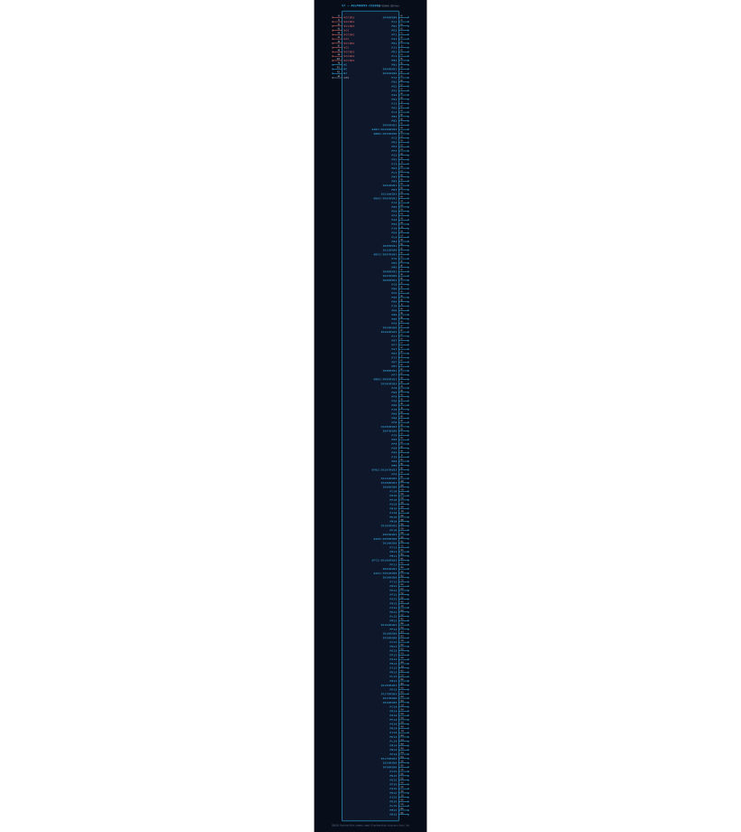
U1 · AGLP060V5-CSG201 (CSP-201(8x8))A1VCCIB1A2IO64RSB1A3GAB2/IO209RSA4IO210RSB3A5IO12RSB0A6IO47RSB0A7IO54RSB0A8GBB2/IO65RSBA9IO206RSB3A10IO208RSB3A11GAA0/IO00RSBA12GAA1/IO01RSBA13IO10RSB0A14IO17RSB0A15IO24RSB0B1IO49RSB0B2IO45RSB0B3GBB0/IO59RSBB4GBA2/IO63RSBB5GBC2/IO67RSBB6IO66RSB1B7IO203RSB3B8IO205RSB3B9IO07RSB0B10IO06RSB0B11IO14RSB0B12IO20RSB0B13IO29RSB0B14IO34RSB0B15IO30RSB0C1PC1C2PC2C3PC3C4PC4C5PC5C6PC6C7PC7C8PC8C9PC9C10PC10C11PC11C12PC12C13PC13C14PC14C15PC15D1PD1D2PD2D3PD3D4PD4D5PD5D6PD6D7PD7D8PD8D9PD9D10PD10D11PD11D12PD12D13PD13D14PD14D15PD15E1PE1E2PE2E3PE3E4PE4E12PE12E13PE13E14PE14E15PE15F1PF1F2PF2F3PF3F4PF4F6PF6F7PF7F8PF8F9PF9F10PF10F12PF12F13PF13F14PF14F15PF15G1PG1G2PG2G3PG3G4PG4G6PG6G7PG7G8PG8G9PG9G10PG10G12PG12G13PG13G14PG14G15PG15H1PH1H2PH2H3PH3H4PH4H6PH6H7PH7H8PH8R15PR15R14IO175RSB3R13IO178RSB3R12NCR11IO92RSB1R10IO93RSB1R9IO122RSB2R8VCCIB1R7VCCR6VCCIB2R5VCCR4VCCIB2R3PR3R2VCCR1VCCIB3P15NCP14PP14P13PP13P12PP12P11PP11P10PP10P9PP9P8PP8P7PP7P6PP6P5IO90RSB1P4NCP3IO91RSB1P2IO95RSB1P1VCCIB1N15VCCIB3N14PN14N13IO199RSB3N12IO184RSB3N11GFC2/IO186RSN10IO185RSB3N9GFB2/IO187RSN8VCCIB1N7IO88RSB1N6PN6N5GNDN4IO89RSB1N3PN3N2PN2N1PN1M15PM15M14PM14M13PM13M12PM12M11PM11M10PM10M9PM9M8PM8M7PM7M6PM6M5PM5M4PM4M3PM3M2PM2M1PM1L15PL15L14PL14L13PL13L12PL12L4PL4L3PL3L2PL2L1PL1K15PK15K14PK14K13PK13K12PK12K10PK10K9PK9K8PK8K7PK7K6PK6K4PK4K3PK3K2PK2K1PK1J15PJ15J14PJ14J13PJ13J12PJ12J10PJ10J9PJ9J8PJ8J7PJ7J6PJ6J4PJ4J3PJ3J2PJ2J1PJ1H15PH15H14PH14H13PH13H12PH12H10PH10H9PH9Grid Pitch = 2.54mm (IEEE-315)-17.8-12.7-7.6-2.52.57.612.717.8134.6129.5124.5119.4114.3109.2104.199.194.088.983.878.773.768.663.558.453.348.343.238.133.027.922.917.812.77.62.5-2.5-7.6-12.7-17.8-22.9-27.9-33.0-38.1-43.2-48.3-53.3-58.4-63.5-68.6-73.7-78.7-83.8-88.9-94.0-99.1-104.1-109.2-114.3-119.4-124.5-129.5-134.6mm
2. 2D-FOOTPRINT
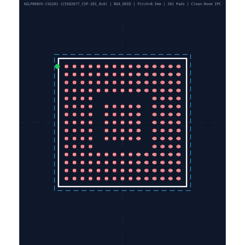
A1B1C1D1E1F1G1H1J1K1L1M1N1P1R1A2B2C2D2E2F2G2H2J2K2L2M2N2P2R2A3B3C3D3E3F3G3H3J3K3L3M3N3P3R3A4B4C4D4E4F4G4H4J4K4L4M4N4P4R4A5B5C5D5M5N5P5R5A6B6C6D6F6G6H6J6K6M6N6P6R6A7B7C7D7F7G7H7J7K7M7N7P7R7A8B8C8D8F8G8H8J8K8M8N8P8R8A9B9C9D9F9G9H9J9K9M9N9P9R9A10B10C10D10F10G10H10J10K10M10N10P10R10A11B11C11D11M11N11P11R11A12B12C12D12E12F12G12H12J12K12L12M12N12P12R12A13B13C13D13E13F13G13H13J13K13L13M13N13P13R13A14B14C14D14E14F14G14H14J14K14L14M14N14P14R14A15B15C15D15E15F15G15H15J15K15L15M15N15P15R15E=8.00mm · Pitch e=0.50mmD=8.00mm-6-5-4-3-2-101234566543210-1-2-3-4-5-6mm
3. 3D-MODELL
Gehäusekörper: 8.00mm × 8.00mm · Raster: 0.50mm · Linealschritt: 1.00mmSynchronisiert <100ms

Synchronisierte Pinbelegung (Symbol / 2D / 3D) (201/201)

Klicken oder berühren Sie einen Pin, um ihn zeitgleich in Symbol, Footprint und 3D hervorzuheben
PinSymbolTypFunktionsbeschreibung (DE)
A1VCCIB1PowerVersorgungsspannungseingang (VCCIB1 — 1.2 V to 1.5 V)
A2IO64RSB1I/OMultiplex-I/O- & Peripherie-Pin IO64RSB1 (General)
A3GAB2/IO209RSB3I/OMultiplex-I/O- & Peripherie-Pin GAB2/IO209RSB3 (General)
A4IO210RSB3I/OMultiplex-I/O- & Peripherie-Pin IO210RSB3 (General)
A5IO12RSB0I/OMultiplex-I/O- & Peripherie-Pin IO12RSB0 (General)
A6IO47RSB0I/OMultiplex-I/O- & Peripherie-Pin IO47RSB0 (General)
A7IO54RSB0I/OMultiplex-I/O- & Peripherie-Pin IO54RSB0 (General)
A8GBB2/IO65RSB1I/OMultiplex-I/O- & Peripherie-Pin GBB2/IO65RSB1 (General)
A9IO206RSB3I/OMultiplex-I/O- & Peripherie-Pin IO206RSB3 (General)
A10IO208RSB3I/OMultiplex-I/O- & Peripherie-Pin IO208RSB3 (General)
A11GAA0/IO00RSB0I/OMultiplex-I/O- & Peripherie-Pin GAA0/IO00RSB0 (General)
A12GAA1/IO01RSB0I/OMultiplex-I/O- & Peripherie-Pin GAA1/IO01RSB0 (General)
A13IO10RSB0I/OMultiplex-I/O- & Peripherie-Pin IO10RSB0 (General)
A14IO17RSB0I/OMultiplex-I/O- & Peripherie-Pin IO17RSB0 (General)
A15IO24RSB0I/OMultiplex-I/O- & Peripherie-Pin IO24RSB0 (General)
B1IO49RSB0I/OMultiplex-I/O- & Peripherie-Pin IO49RSB0 (General)
B2IO45RSB0I/OMultiplex-I/O- & Peripherie-Pin IO45RSB0 (General)
B3GBB0/IO59RSB0I/OMultiplex-I/O- & Peripherie-Pin GBB0/IO59RSB0 (General)
B4GBA2/IO63RSB1I/OMultiplex-I/O- & Peripherie-Pin GBA2/IO63RSB1 (General)
B5GBC2/IO67RSB1I/OMultiplex-I/O- & Peripherie-Pin GBC2/IO67RSB1 (General)
B6IO66RSB1I/OMultiplex-I/O- & Peripherie-Pin IO66RSB1 (General)
B7IO203RSB3I/OMultiplex-I/O- & Peripherie-Pin IO203RSB3 (General)
B8IO205RSB3I/OMultiplex-I/O- & Peripherie-Pin IO205RSB3 (General)
B9IO07RSB0I/OMultiplex-I/O- & Peripherie-Pin IO07RSB0 (General)
B10IO06RSB0I/OMultiplex-I/O- & Peripherie-Pin IO06RSB0 (General)
B11IO14RSB0I/OMultiplex-I/O- & Peripherie-Pin IO14RSB0 (General)
B12IO20RSB0I/OMultiplex-I/O- & Peripherie-Pin IO20RSB0 (General)
B13IO29RSB0I/OMultiplex-I/O- & Peripherie-Pin IO29RSB0 (General)
B14IO34RSB0I/OMultiplex-I/O- & Peripherie-Pin IO34RSB0 (General)
B15IO30RSB0I/OMultiplex-I/O- & Peripherie-Pin IO30RSB0 (General)
C1PC1I/OMultiplex-I/O- & Peripherie-Pin PC1 (General)
C2PC2I/OMultiplex-I/O- & Peripherie-Pin PC2 (General)
C3PC3I/OMultiplex-I/O- & Peripherie-Pin PC3 (General)
C4PC4I/OMultiplex-I/O- & Peripherie-Pin PC4 (General)
C5PC5I/OMultiplex-I/O- & Peripherie-Pin PC5 (General)
C6PC6I/OMultiplex-I/O- & Peripherie-Pin PC6 (General)
C7PC7I/OMultiplex-I/O- & Peripherie-Pin PC7 (General)
C8PC8I/OMultiplex-I/O- & Peripherie-Pin PC8 (General)
C9PC9I/OMultiplex-I/O- & Peripherie-Pin PC9 (General)
C10PC10I/OMultiplex-I/O- & Peripherie-Pin PC10 (General)
C11PC11I/OMultiplex-I/O- & Peripherie-Pin PC11 (General)
C12PC12I/OMultiplex-I/O- & Peripherie-Pin PC12 (General)
C13PC13I/OMultiplex-I/O- & Peripherie-Pin PC13 (General)
C14PC14I/OMultiplex-I/O- & Peripherie-Pin PC14 (General)
C15PC15I/OMultiplex-I/O- & Peripherie-Pin PC15 (General)
D1PD1I/OMultiplex-I/O- & Peripherie-Pin PD1 (General)
D2PD2I/OMultiplex-I/O- & Peripherie-Pin PD2 (General)
D3PD3I/OMultiplex-I/O- & Peripherie-Pin PD3 (General)
D4PD4I/OMultiplex-I/O- & Peripherie-Pin PD4 (General)
D5PD5I/OMultiplex-I/O- & Peripherie-Pin PD5 (General)
D6PD6I/OMultiplex-I/O- & Peripherie-Pin PD6 (General)
D7PD7I/OMultiplex-I/O- & Peripherie-Pin PD7 (General)
D8PD8I/OMultiplex-I/O- & Peripherie-Pin PD8 (General)
D9PD9I/OMultiplex-I/O- & Peripherie-Pin PD9 (General)
D10PD10I/OMultiplex-I/O- & Peripherie-Pin PD10 (General)
D11PD11I/OMultiplex-I/O- & Peripherie-Pin PD11 (General)
D12PD12I/OMultiplex-I/O- & Peripherie-Pin PD12 (General)
D13PD13I/OMultiplex-I/O- & Peripherie-Pin PD13 (General)
D14PD14I/OMultiplex-I/O- & Peripherie-Pin PD14 (General)
D15PD15I/OMultiplex-I/O- & Peripherie-Pin PD15 (General)
E1PE1I/OMultiplex-I/O- & Peripherie-Pin PE1 (General)
E2PE2I/OMultiplex-I/O- & Peripherie-Pin PE2 (General)
E3PE3I/OMultiplex-I/O- & Peripherie-Pin PE3 (General)
E4PE4I/OMultiplex-I/O- & Peripherie-Pin PE4 (General)
E12PE12I/OMultiplex-I/O- & Peripherie-Pin PE12 (General)
E13PE13I/OMultiplex-I/O- & Peripherie-Pin PE13 (General)
E14PE14I/OMultiplex-I/O- & Peripherie-Pin PE14 (General)
E15PE15I/OMultiplex-I/O- & Peripherie-Pin PE15 (General)
F1PF1I/OMultiplex-I/O- & Peripherie-Pin PF1 (General)
F2PF2I/OMultiplex-I/O- & Peripherie-Pin PF2 (General)
F3PF3I/OMultiplex-I/O- & Peripherie-Pin PF3 (General)
F4PF4I/OMultiplex-I/O- & Peripherie-Pin PF4 (General)
F6PF6I/OMultiplex-I/O- & Peripherie-Pin PF6 (General)
F7PF7I/OMultiplex-I/O- & Peripherie-Pin PF7 (General)
F8PF8I/OMultiplex-I/O- & Peripherie-Pin PF8 (General)
F9PF9I/OMultiplex-I/O- & Peripherie-Pin PF9 (General)
F10PF10I/OMultiplex-I/O- & Peripherie-Pin PF10 (General)
F12PF12I/OMultiplex-I/O- & Peripherie-Pin PF12 (General)
F13PF13I/OMultiplex-I/O- & Peripherie-Pin PF13 (General)
F14PF14I/OMultiplex-I/O- & Peripherie-Pin PF14 (General)
F15PF15I/OMultiplex-I/O- & Peripherie-Pin PF15 (General)
G1PG1I/OMultiplex-I/O- & Peripherie-Pin PG1 (General)
G2PG2I/OMultiplex-I/O- & Peripherie-Pin PG2 (General)
G3PG3I/OMultiplex-I/O- & Peripherie-Pin PG3 (General)
G4PG4I/OMultiplex-I/O- & Peripherie-Pin PG4 (General)
G6PG6I/OMultiplex-I/O- & Peripherie-Pin PG6 (General)
G7PG7I/OMultiplex-I/O- & Peripherie-Pin PG7 (General)
G8PG8I/OMultiplex-I/O- & Peripherie-Pin PG8 (General)
G9PG9I/OMultiplex-I/O- & Peripherie-Pin PG9 (General)
G10PG10I/OMultiplex-I/O- & Peripherie-Pin PG10 (General)
G12PG12I/OMultiplex-I/O- & Peripherie-Pin PG12 (General)
G13PG13I/OMultiplex-I/O- & Peripherie-Pin PG13 (General)
G14PG14I/OMultiplex-I/O- & Peripherie-Pin PG14 (General)
G15PG15I/OMultiplex-I/O- & Peripherie-Pin PG15 (General)
H1PH1I/OMultiplex-I/O- & Peripherie-Pin PH1 (General)
H2PH2I/OMultiplex-I/O- & Peripherie-Pin PH2 (General)
H3PH3I/OMultiplex-I/O- & Peripherie-Pin PH3 (General)
H4PH4I/OMultiplex-I/O- & Peripherie-Pin PH4 (General)
H6PH6I/OMultiplex-I/O- & Peripherie-Pin PH6 (General)
H7PH7I/OMultiplex-I/O- & Peripherie-Pin PH7 (General)
H8PH8I/OMultiplex-I/O- & Peripherie-Pin PH8 (General)
H9PH9I/OMultiplex-I/O- & Peripherie-Pin PH9 (General)
H10PH10I/OMultiplex-I/O- & Peripherie-Pin PH10 (General)
H12PH12I/OMultiplex-I/O- & Peripherie-Pin PH12 (General)
H13PH13I/OMultiplex-I/O- & Peripherie-Pin PH13 (General)
H14PH14I/OMultiplex-I/O- & Peripherie-Pin PH14 (General)
H15PH15I/OMultiplex-I/O- & Peripherie-Pin PH15 (General)
J1PJ1I/OMultiplex-I/O- & Peripherie-Pin PJ1 (General)
J2PJ2I/OMultiplex-I/O- & Peripherie-Pin PJ2 (General)
J3PJ3I/OMultiplex-I/O- & Peripherie-Pin PJ3 (General)
J4PJ4I/OMultiplex-I/O- & Peripherie-Pin PJ4 (General)
J6PJ6I/OMultiplex-I/O- & Peripherie-Pin PJ6 (General)
J7PJ7I/OMultiplex-I/O- & Peripherie-Pin PJ7 (General)
J8PJ8I/OMultiplex-I/O- & Peripherie-Pin PJ8 (General)
J9PJ9I/OMultiplex-I/O- & Peripherie-Pin PJ9 (General)
J10PJ10I/OMultiplex-I/O- & Peripherie-Pin PJ10 (General)
J12PJ12I/OMultiplex-I/O- & Peripherie-Pin PJ12 (General)
J13PJ13I/OMultiplex-I/O- & Peripherie-Pin PJ13 (General)
J14PJ14I/OMultiplex-I/O- & Peripherie-Pin PJ14 (General)
J15PJ15I/OMultiplex-I/O- & Peripherie-Pin PJ15 (General)
K1PK1I/OMultiplex-I/O- & Peripherie-Pin PK1 (General)
K2PK2I/OMultiplex-I/O- & Peripherie-Pin PK2 (General)
K3PK3I/OMultiplex-I/O- & Peripherie-Pin PK3 (General)
K4PK4I/OMultiplex-I/O- & Peripherie-Pin PK4 (General)
K6PK6I/OMultiplex-I/O- & Peripherie-Pin PK6 (General)
K7PK7I/OMultiplex-I/O- & Peripherie-Pin PK7 (General)
K8PK8I/OMultiplex-I/O- & Peripherie-Pin PK8 (General)
K9PK9I/OMultiplex-I/O- & Peripherie-Pin PK9 (General)
K10PK10I/OMultiplex-I/O- & Peripherie-Pin PK10 (General)
K12PK12I/OMultiplex-I/O- & Peripherie-Pin PK12 (General)
K13PK13I/OMultiplex-I/O- & Peripherie-Pin PK13 (General)
K14PK14I/OMultiplex-I/O- & Peripherie-Pin PK14 (General)
K15PK15I/OMultiplex-I/O- & Peripherie-Pin PK15 (General)
L1PL1I/OMultiplex-I/O- & Peripherie-Pin PL1 (General)
L2PL2I/OMultiplex-I/O- & Peripherie-Pin PL2 (General)
L3PL3I/OMultiplex-I/O- & Peripherie-Pin PL3 (General)
L4PL4I/OMultiplex-I/O- & Peripherie-Pin PL4 (General)
L12PL12I/OMultiplex-I/O- & Peripherie-Pin PL12 (General)
L13PL13I/OMultiplex-I/O- & Peripherie-Pin PL13 (General)
L14PL14I/OMultiplex-I/O- & Peripherie-Pin PL14 (General)
L15PL15I/OMultiplex-I/O- & Peripherie-Pin PL15 (General)
M1PM1I/OMultiplex-I/O- & Peripherie-Pin PM1 (General)
M2PM2I/OMultiplex-I/O- & Peripherie-Pin PM2 (General)
M3PM3I/OMultiplex-I/O- & Peripherie-Pin PM3 (General)
M4PM4I/OMultiplex-I/O- & Peripherie-Pin PM4 (General)
M5PM5I/OMultiplex-I/O- & Peripherie-Pin PM5 (General)
M6PM6I/OMultiplex-I/O- & Peripherie-Pin PM6 (General)
M7PM7I/OMultiplex-I/O- & Peripherie-Pin PM7 (General)
M8PM8I/OMultiplex-I/O- & Peripherie-Pin PM8 (General)
M9PM9I/OMultiplex-I/O- & Peripherie-Pin PM9 (General)
M10PM10I/OMultiplex-I/O- & Peripherie-Pin PM10 (General)
M11PM11I/OMultiplex-I/O- & Peripherie-Pin PM11 (General)
M12PM12I/OMultiplex-I/O- & Peripherie-Pin PM12 (General)
M13PM13I/OMultiplex-I/O- & Peripherie-Pin PM13 (General)
M14PM14I/OMultiplex-I/O- & Peripherie-Pin PM14 (General)
M15PM15I/OMultiplex-I/O- & Peripherie-Pin PM15 (General)
N1PN1I/OMultiplex-I/O- & Peripherie-Pin PN1 (General)
N2PN2I/OMultiplex-I/O- & Peripherie-Pin PN2 (General)
N3PN3I/OMultiplex-I/O- & Peripherie-Pin PN3 (General)
N4IO89RSB1I/OMultiplex-I/O- & Peripherie-Pin IO89RSB1 (General)
N5GNDGNDMasseanschluss (GND)
N6PN6I/OMultiplex-I/O- & Peripherie-Pin PN6 (General)
N7IO88RSB1I/OMultiplex-I/O- & Peripherie-Pin IO88RSB1 (General)
N8VCCIB1PowerVersorgungsspannungseingang (VCCIB1 — 1.2 V to 1.5 V)
N9GFB2/IO187RSB3I/OMultiplex-I/O- & Peripherie-Pin GFB2/IO187RSB3 (General)
N10IO185RSB3I/OMultiplex-I/O- & Peripherie-Pin IO185RSB3 (General)
N11GFC2/IO186RSB3I/OMultiplex-I/O- & Peripherie-Pin GFC2/IO186RSB3 (General)
N12IO184RSB3I/OMultiplex-I/O- & Peripherie-Pin IO184RSB3 (General)
N13IO199RSB3I/OMultiplex-I/O- & Peripherie-Pin IO199RSB3 (General)
N14PN14I/OMultiplex-I/O- & Peripherie-Pin PN14 (General)
N15VCCIB3PowerVersorgungsspannungseingang (VCCIB3 — 1.2 V to 1.5 V)
P1VCCIB1PowerVersorgungsspannungseingang (VCCIB1 — 1.2 V to 1.5 V)
P2IO95RSB1I/OMultiplex-I/O- & Peripherie-Pin IO95RSB1 (General)
P3IO91RSB1I/OMultiplex-I/O- & Peripherie-Pin IO91RSB1 (General)
P4NCI/OMultiplex-I/O- & Peripherie-Pin NC (General)
P5IO90RSB1I/OMultiplex-I/O- & Peripherie-Pin IO90RSB1 (General)
P6PP6I/OMultiplex-I/O- & Peripherie-Pin PP6 (General)
P7PP7I/OMultiplex-I/O- & Peripherie-Pin PP7 (General)
P8PP8I/OMultiplex-I/O- & Peripherie-Pin PP8 (General)
P9PP9I/OMultiplex-I/O- & Peripherie-Pin PP9 (General)
P10PP10I/OMultiplex-I/O- & Peripherie-Pin PP10 (General)
P11PP11I/OMultiplex-I/O- & Peripherie-Pin PP11 (General)
P12PP12I/OMultiplex-I/O- & Peripherie-Pin PP12 (General)
P13PP13I/OMultiplex-I/O- & Peripherie-Pin PP13 (General)
P14PP14I/OMultiplex-I/O- & Peripherie-Pin PP14 (General)
P15NCI/OMultiplex-I/O- & Peripherie-Pin NC (General)
R1VCCIB3PowerVersorgungsspannungseingang (VCCIB3 — 1.2 V to 1.5 V)
R2VCCPowerVersorgungsspannungseingang (VCC — 1.2 V to 1.5 V)
R3PR3I/OMultiplex-I/O- & Peripherie-Pin PR3 (General)
R4VCCIB2PowerVersorgungsspannungseingang (VCCIB2 — 1.2 V to 1.5 V)
R5VCCPowerVersorgungsspannungseingang (VCC — 1.2 V to 1.5 V)
R6VCCIB2PowerVersorgungsspannungseingang (VCCIB2 — 1.2 V to 1.5 V)
R7VCCPowerVersorgungsspannungseingang (VCC — 1.2 V to 1.5 V)
R8VCCIB1PowerVersorgungsspannungseingang (VCCIB1 — 1.2 V to 1.5 V)
R9IO122RSB2I/OMultiplex-I/O- & Peripherie-Pin IO122RSB2 (General)
R10IO93RSB1I/OMultiplex-I/O- & Peripherie-Pin IO93RSB1 (General)
R11IO92RSB1I/OMultiplex-I/O- & Peripherie-Pin IO92RSB1 (General)
R12NCI/OMultiplex-I/O- & Peripherie-Pin NC (General)
R13IO178RSB3I/OMultiplex-I/O- & Peripherie-Pin IO178RSB3 (General)
R14IO175RSB3I/OMultiplex-I/O- & Peripherie-Pin IO175RSB3 (General)
R15PR15I/OMultiplex-I/O- & Peripherie-Pin PR15 (General)
PIN A1 VCCIB1
Power
Versorgungsspannungseingang (VCCIB1 — 1.2 V to 1.5 V)
Designhinweis: GND
IPC-7351B Lötdichte & Spannweite C/G/Z Konfigurator

Live-PDF-Datenblatt-Viewer & Technische Zeichnungen (6 Standardzeichnungen + 2 Extrahierte Abbildungen)

Original-Datenblatt direkt im Browser lesen oder Zeichnungen im Vollbildmodus vergrößern
PDF in neuem Fenster öffnen ↗PDF-Datenblatt lesen (.pdf)
PDF VIEWEROffizielles Datenblatt: AGLP060V5-CSG201 (MICROCHIP · CSP-201(8x8))
Im eingebetteten PDF-Viewer unten scrollen, suchen (Strg+F) oder vergrößern
1. Reales 3D-GehäusemodellREPRESENTATIVE
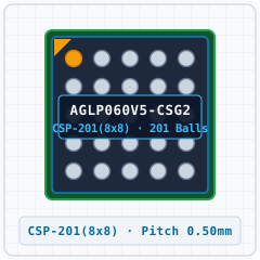
AGLP060V5-CSG201 (CSP-201(8x8)) - 1. Reales 3D-Gehäusemodell
Detaillierter 3D-VolumenkörperVergrößern ›
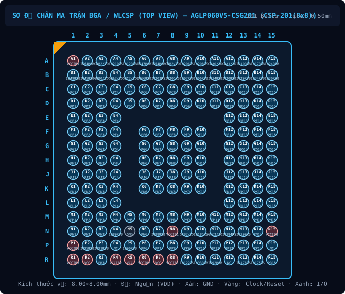
2. Standard-Pinbelegung (Draufsicht)CLEANROOM PINOUT
AGLP060V5-CSG201 (CSP-201(8x8)) - 2. Standard-Pinbelegung (Draufsicht)
Konforme Pinanordnung (201 Pins)Vergrößern ›
3. Original-Datenblatt-PinoutPDF PINOUT
AGLP060V5-CSG201 (CSP-201(8x8)) - 3. Original-Datenblatt-Pinout
Unbeschnittenes DatenblattdiagrammVergrößern ›
4. Gehäuseabmessungen (D×E×A)PACKAGE DIMENSIONS
AGLP060V5-CSG201 (CSP-201(8x8)) - 4. Gehäuseabmessungen (D×E×A)
CSP-201(8x8) · 8.00×8.00mm · Raster 0.50mmVergrößern ›
5. Empfohlener PCB-FootprintLAND PATTERN
AGLP060V5-CSG201 (CSP-201(8x8)) - 5. Empfohlener PCB-Footprint
IPC-7351B Land Pattern (201 Pads)Vergrößern ›
6. Typische ApplikationsschaltungSCHEMATIC
AGLP060V5-CSG201 (CSP-201(8x8)) - 6. Typische Applikationsschaltung
Typical Application SchematicVergrößern ›
Originale Datenblatt-Pinouts & Technische Zeichnungen (2 Abb. · Seite 1/1)
Zeige 1–2 von 2 unbeschnittenen Originalzeichnungen für AGLP030 / AGLP060
P98 · p98_fig011543×1613px
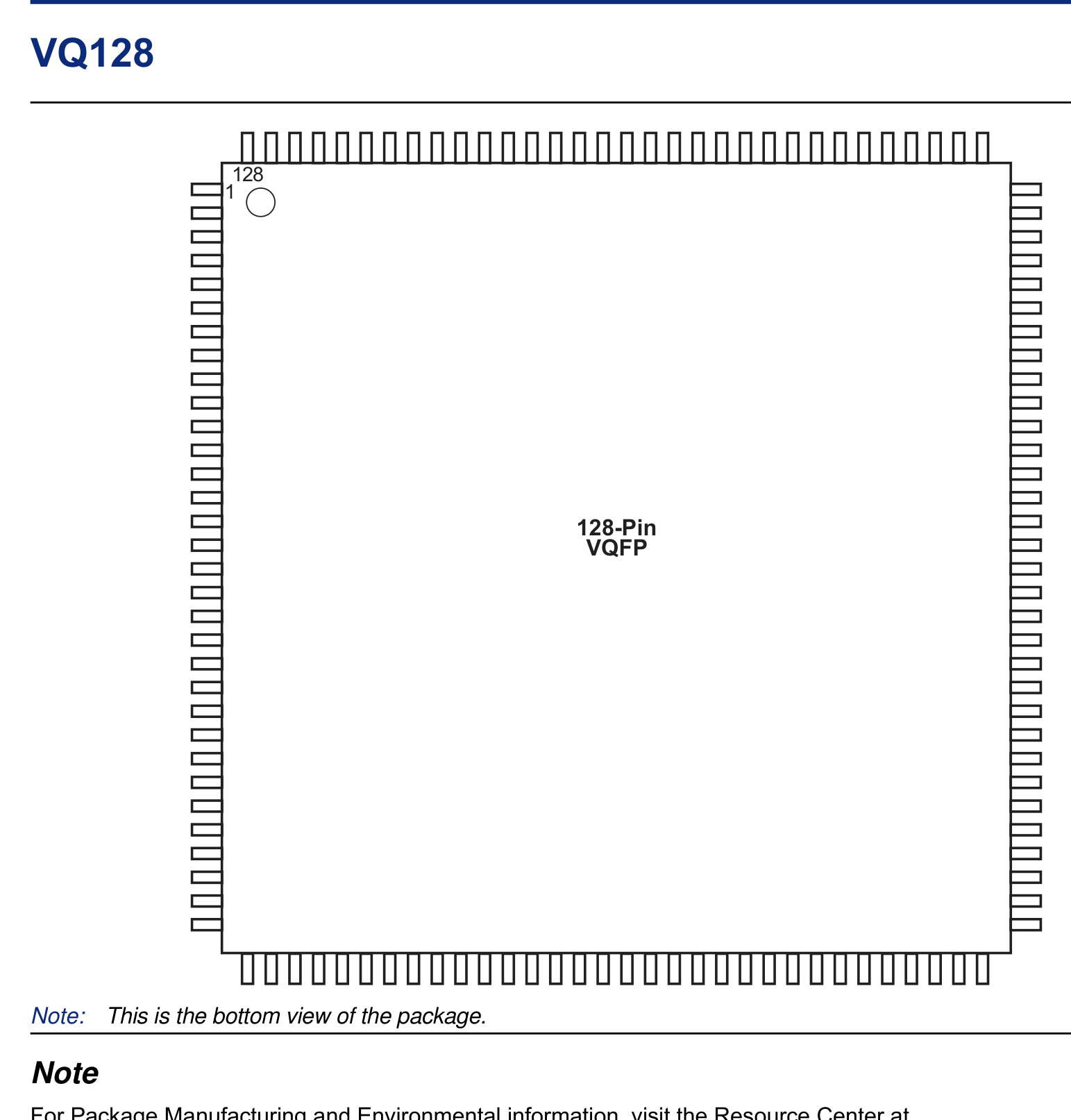
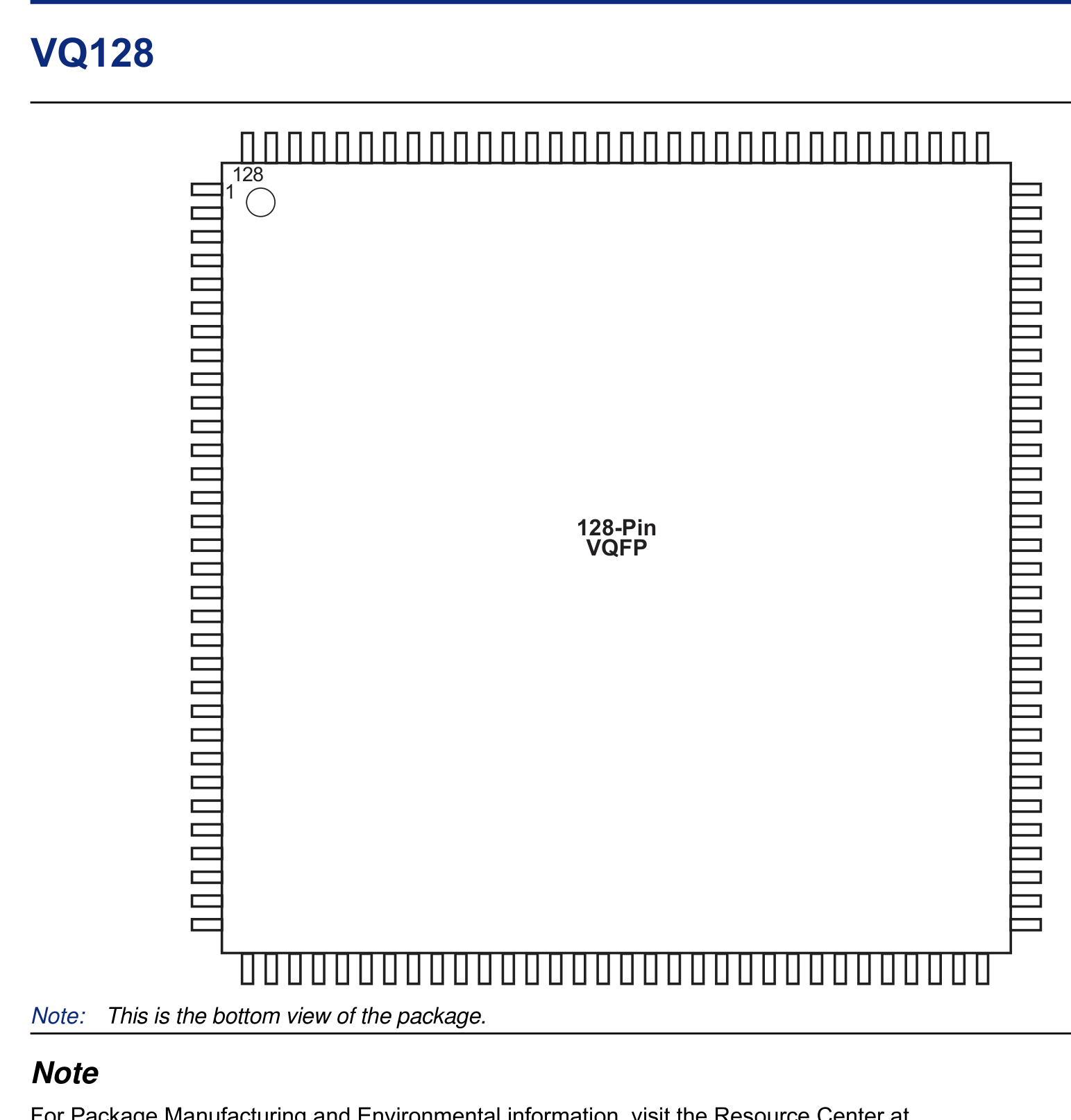
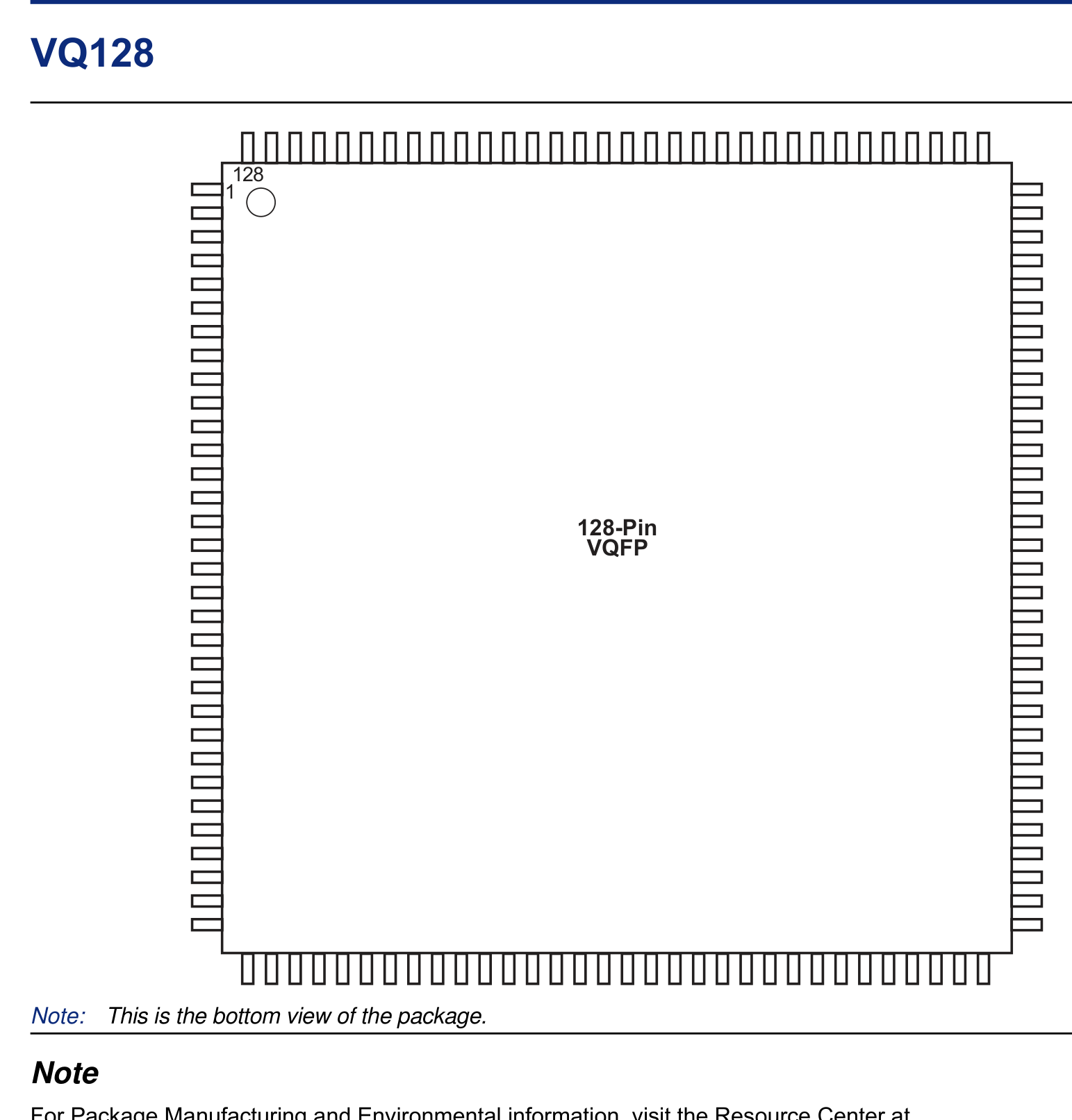
AGLP060V5-CSG201 (CSP-201(8x8)) — Pin information is in the "Pin Descriptions" chapter of the IGLOO PLUS FPGA Fabric User’s Guide.
Pin information is in the "Pin Descriptions" chapter of the IGLOO PLUS FPGA Fabric User’s Guide.
P98 · p98_fig01P98
AGLP060V5-CSG201 (CSP-201(8x8)) — Datasheet Page 98 (p98_fig01)
Datasheet Page 98 (p98_fig01)

Elektrische Spezifikationen & Bauteildetails (AGLP060V5-CSG201)

Automatisch aus dem Datenblatt extrahierte Funktionsbeschreibung, Abmessungen, Betriebsspannungsbereich und Schnittstellen (DE)
Standard-Elektronik- & Steckverbinderbauteil
Detaillierte Übersicht:AGLP060V5-CSG201 (CSP-201(8x8)) ist ein 201-poliges Standard-Elektronik- & Steckverbinderbauteil mit den Gehäuseabmessungen 8.00 × 8.00 × 0.55 mm (Pin-Raster e = 0.50 mm). Ausgelegt für 1.2 V to 1.5 V Versorgungsspannung, 0°C to +85°C Temperaturbereich und JTAG / SWD Schnittstellen.
BetriebsversorgungsspannungV_CC / V_DD
1.2 V to 1.5 V
100nF + 10µF X7R Stützkondensatoren < 2mm am Versorgungspin platzieren
UmgebungstemperaturbereichT_A
0°C to +85°C
Industrieller Temperaturbereich; T_J(max) = +125°C
Takt- & Funkfrequenzf_CLK / f_RF
250 MHz
Aus offiziellen PDF-Datenblatttabellen extrahiert
Strom- & LeistungsdatenI_OUT / I_CC
I_GPIO(max) = ±20 mA / pin | I_VDD(total) ≤ 150 mA
Maximal zulässigen Pin-Strom beachten
Gehäuseabmessungen (D × E × A)D × E × A
8.00 × 8.00 × 0.55 mm (A1=0.18 mm)
Gehäusefamilie: WLCSP (CSP-201(8x8))
Pinanzahl & RastermaßN / e
201 Pins | Pitch e = 0.50 mm (19.7 mil)
Nach IPC-7351B Mittenabstand C normalisiert
Integrierte BusschnittstellenBuses
JTAG / SWD
4-Wege-Synchronisation (Symbol ↔ Pinout ↔ 2D ↔ 3D)
Lötprofil & FeuchteempfindlichkeitIPC / MSL
IPC-7351B Level B | J-STD-020 (Peak 260°C) | MSL-3
60% Pastenmasken-Segmentierung auf dem Thermal-Pad
Technischer Sicherheitshinweis: Vor der SMT-Bestückung die Pin-1-Markierung auf dem Bestückungsdruck prüfen.
Technischer Sicherheitshinweis: Thermal-Pad über Ø0.3mm Thermodurchkontaktierungen niederimpedant an die GND-Lage anbinden.

5-Punkte-Industriestandardprüfung

Automatische Geometrie- und Regelprüfung vor dem Dateiexport
5/5 BESTANDEN
IEEE-315 Symbol201 Pins automatisch nach Bussen gruppiert
OK
IPC-7351B Footprint201 Pads · Raster 0.50mm
OK
IPC-7525 60% LotpastenfensterReflow 1:1 Standard
OK
DFM-Fertigungsregeln (JLCPCB / PCBWay)Min. Pad-Abstand: 0.25mm
OK
3D STEP AP214 & GLBKoordinatenursprung deckungsgleich (0,0,0)
OK

Praxisverifikation & Ingenieurbewertungen

Automatisch aus dem Datenblatt extrahierte Funktionsbeschreibung, Abmessungen, Betriebsspannungsbereich und Schnittstellen
5.00 PCB Verified

Mechanische Abmessungen & Land Pattern (CSP-201(8x8))

Aus dem Datenblatt extrahiert & nach IPC-7351B normiert
mm
Gehäusekörper (D × E)Nominal
8.00 × 8.00 mm
Höhe (A) & Raster (e)IPC-7351B
A=0.55mm · e=0.50mm
Pad-Abmessungen (W × L)Level B
0.24 × 0.24 mm
Pins / Gesamt-PadsTopology
201P / 201Pad (BGA_GRID)

Empfohlene Peripherie-BOM & Pin-kompatible Ersatztypen (Drop-in)

Passive Begleitbauteile gemäß Referenzschaltung sowie 1:1 pin-kompatible Alternativen
DFM READY
Bauteilbezeichner / Ersatz-MPNWert / GehäuseFunktion & PCB-Layout-Regel
N/A
BOM
Gemäß Applikationsschaltung
CSP-201(8x8)
Leiterbahnbreiten für Nennstrom dimensionieren und IPC-2221 Isolationsabstände einhalten.

Häufig gestellte technische Fragen (FAQ) — AGLP060V5-CSG201 (CSP-201(8x8))

Schnellantworten zu Pinbelegung, IPC-7351B Land-Pattern-Abmessungen und CAD-Exportformaten
IPC-7351B / IEEE-315

Wie lautet die Pinbelegung (Pinout) und Versorgungsspannung des AGLP060V5-CSG201 (CSP-201(8x8))?

Das Bauteil AGLP060V5-CSG201 von MICROCHIP im CSP-201(8x8)-Gehäuse besitzt 201 Pins mit einem Rastermaß (Pitch) von 0.50 mm und einem Betriebsspannungsbereich VCC von 1.2 V to 1.5 V. Wichtige Pins: A1 (VCCIB1: Versorgungsspannungseingang (VCCIB1 — 1.2 V to 1.5 V)), A2 (IO64RSB1: Multiplex-I/O- & Peripherie-Pin IO64RSB1 (General)), A3 (GAB2/IO209RSB3: Multiplex-I/O- & Peripherie-Pin GAB2/IO209RSB3 (General)), A4 (IO210RSB3: Multiplex-I/O- & Peripherie-Pin IO210RSB3 (General)), A5 (IO12RSB0: Multiplex-I/O- & Peripherie-Pin IO12RSB0 (General)), A6 (IO47RSB0: Multiplex-I/O- & Peripherie-Pin IO47RSB0 (General)).

Welche IPC-7351B Land-Pattern-Abmessungen hat der AGLP060V5-CSG201?

Gemäß Datenblatt und IPC-7351B (Density Level B Nominal) betragen die Gehäusemaße des AGLP060V5-CSG201 (CSP-201(8x8)) 8.00 × 8.00 mm bei einem Pitch e = 0.50 mm und 201 Kupfer-Pads.

Wo können KiCad (.kicad_mod, .kicad_sym), Fusion 360 (.lbr) und 3D-STEP-Modelle für AGLP060V5-CSG201 heruntergeladen werden?

Auf dieser Seite können Sie das vollständig verifizierte CAD-Bibliothekspaket für AGLP060V5-CSG201 (MICROCHIP, CSP-201(8x8)) unter der Open-Hardware-Lizenz CERN-OHL-P-2.0 kostenlos herunterladen: KiCad 8 Footprint (.kicad_mod), Schaltplansymbol (.kicad_sym), Fusion 360 / Eagle (.lbr) und 3D STEP AP214 / WebGL GLB.

Statischer Referenzanhang: Pinbelegungstabelle (201 Pins) & AGLP030 / AGLP060 VariantenStatische Tabelle aufklappen
Pin-Nr.SignalnameElektrischer TypFunktionsbeschreibung & Schaltungshinweise
A1VCCIB1Power_InPositiver Versorgungseingang (VCCIB1) im Spannungsbereich 1.2 V to 1.5 V (Max. 1.5V).
A2IO64RSB1Digital_IOSignalanschluss IO64RSB1 (Richtung: I/O, Spannungsbereich: 1.2 V to 1.5 V). Alternative Multiplex-Funktionen: IO64RSB1. Unterstützte Bus-Schnittstellen: General.
A3GAB2/IO209RSB3Digital_IOSignalanschluss GAB2/IO209RSB3 (Richtung: I/O, Spannungsbereich: 1.2 V to 1.5 V). Alternative Multiplex-Funktionen: GAB2/IO209RSB3. Unterstützte Bus-Schnittstellen: General.
A4IO210RSB3Digital_IOSignalanschluss IO210RSB3 (Richtung: I/O, Spannungsbereich: 1.2 V to 1.5 V). Alternative Multiplex-Funktionen: IO210RSB3. Unterstützte Bus-Schnittstellen: General.
A5IO12RSB0Digital_IOSignalanschluss IO12RSB0 (Richtung: I/O, Spannungsbereich: 1.2 V to 1.5 V). Alternative Multiplex-Funktionen: IO12RSB0. Unterstützte Bus-Schnittstellen: General.
A6IO47RSB0Digital_IOSignalanschluss IO47RSB0 (Richtung: I/O, Spannungsbereich: 1.2 V to 1.5 V). Alternative Multiplex-Funktionen: IO47RSB0. Unterstützte Bus-Schnittstellen: General.
A7IO54RSB0Digital_IOSignalanschluss IO54RSB0 (Richtung: I/O, Spannungsbereich: 1.2 V to 1.5 V). Alternative Multiplex-Funktionen: IO54RSB0. Unterstützte Bus-Schnittstellen: General.
A8GBB2/IO65RSB1Digital_IOSignalanschluss GBB2/IO65RSB1 (Richtung: I/O, Spannungsbereich: 1.2 V to 1.5 V). Alternative Multiplex-Funktionen: GBB2/IO65RSB1. Unterstützte Bus-Schnittstellen: General.
A9IO206RSB3Digital_IOSignalanschluss IO206RSB3 (Richtung: I/O, Spannungsbereich: 1.2 V to 1.5 V). Alternative Multiplex-Funktionen: IO206RSB3. Unterstützte Bus-Schnittstellen: General.
A10IO208RSB3Digital_IOSignalanschluss IO208RSB3 (Richtung: I/O, Spannungsbereich: 1.2 V to 1.5 V). Alternative Multiplex-Funktionen: IO208RSB3. Unterstützte Bus-Schnittstellen: General.
A11GAA0/IO00RSB0Digital_IOSignalanschluss GAA0/IO00RSB0 (Richtung: I/O, Spannungsbereich: 1.2 V to 1.5 V). Alternative Multiplex-Funktionen: GAA0/IO00RSB0. Unterstützte Bus-Schnittstellen: General.
A12GAA1/IO01RSB0Digital_IOSignalanschluss GAA1/IO01RSB0 (Richtung: I/O, Spannungsbereich: 1.2 V to 1.5 V). Alternative Multiplex-Funktionen: GAA1/IO01RSB0. Unterstützte Bus-Schnittstellen: General.
A13IO10RSB0Digital_IOSignalanschluss IO10RSB0 (Richtung: I/O, Spannungsbereich: 1.2 V to 1.5 V). Alternative Multiplex-Funktionen: IO10RSB0. Unterstützte Bus-Schnittstellen: General.
A14IO17RSB0Digital_IOSignalanschluss IO17RSB0 (Richtung: I/O, Spannungsbereich: 1.2 V to 1.5 V). Alternative Multiplex-Funktionen: IO17RSB0. Unterstützte Bus-Schnittstellen: General.
A15IO24RSB0Digital_IOSignalanschluss IO24RSB0 (Richtung: I/O, Spannungsbereich: 1.2 V to 1.5 V). Alternative Multiplex-Funktionen: IO24RSB0. Unterstützte Bus-Schnittstellen: General.
B1IO49RSB0Digital_IOSignalanschluss IO49RSB0 (Richtung: I/O, Spannungsbereich: 1.2 V to 1.5 V). Alternative Multiplex-Funktionen: IO49RSB0. Unterstützte Bus-Schnittstellen: General.
B2IO45RSB0Digital_IOSignalanschluss IO45RSB0 (Richtung: I/O, Spannungsbereich: 1.2 V to 1.5 V). Alternative Multiplex-Funktionen: IO45RSB0. Unterstützte Bus-Schnittstellen: General.
B3GBB0/IO59RSB0Digital_IOSignalanschluss GBB0/IO59RSB0 (Richtung: I/O, Spannungsbereich: 1.2 V to 1.5 V). Alternative Multiplex-Funktionen: GBB0/IO59RSB0. Unterstützte Bus-Schnittstellen: General.
B4GBA2/IO63RSB1Digital_IOSignalanschluss GBA2/IO63RSB1 (Richtung: I/O, Spannungsbereich: 1.2 V to 1.5 V). Alternative Multiplex-Funktionen: GBA2/IO63RSB1. Unterstützte Bus-Schnittstellen: General.
B5GBC2/IO67RSB1Digital_IOSignalanschluss GBC2/IO67RSB1 (Richtung: I/O, Spannungsbereich: 1.2 V to 1.5 V). Alternative Multiplex-Funktionen: GBC2/IO67RSB1. Unterstützte Bus-Schnittstellen: General.
B6IO66RSB1Digital_IOSignalanschluss IO66RSB1 (Richtung: I/O, Spannungsbereich: 1.2 V to 1.5 V). Alternative Multiplex-Funktionen: IO66RSB1. Unterstützte Bus-Schnittstellen: General.
B7IO203RSB3Digital_IOSignalanschluss IO203RSB3 (Richtung: I/O, Spannungsbereich: 1.2 V to 1.5 V). Alternative Multiplex-Funktionen: IO203RSB3. Unterstützte Bus-Schnittstellen: General.
B8IO205RSB3Digital_IOSignalanschluss IO205RSB3 (Richtung: I/O, Spannungsbereich: 1.2 V to 1.5 V). Alternative Multiplex-Funktionen: IO205RSB3. Unterstützte Bus-Schnittstellen: General.
B9IO07RSB0Digital_IOSignalanschluss IO07RSB0 (Richtung: I/O, Spannungsbereich: 1.2 V to 1.5 V). Alternative Multiplex-Funktionen: IO07RSB0. Unterstützte Bus-Schnittstellen: General.
B10IO06RSB0Digital_IOSignalanschluss IO06RSB0 (Richtung: I/O, Spannungsbereich: 1.2 V to 1.5 V). Alternative Multiplex-Funktionen: IO06RSB0. Unterstützte Bus-Schnittstellen: General.
B11IO14RSB0Digital_IOSignalanschluss IO14RSB0 (Richtung: I/O, Spannungsbereich: 1.2 V to 1.5 V). Alternative Multiplex-Funktionen: IO14RSB0. Unterstützte Bus-Schnittstellen: General.
B12IO20RSB0Digital_IOSignalanschluss IO20RSB0 (Richtung: I/O, Spannungsbereich: 1.2 V to 1.5 V). Alternative Multiplex-Funktionen: IO20RSB0. Unterstützte Bus-Schnittstellen: General.
B13IO29RSB0Digital_IOSignalanschluss IO29RSB0 (Richtung: I/O, Spannungsbereich: 1.2 V to 1.5 V). Alternative Multiplex-Funktionen: IO29RSB0. Unterstützte Bus-Schnittstellen: General.
B14IO34RSB0Digital_IOSignalanschluss IO34RSB0 (Richtung: I/O, Spannungsbereich: 1.2 V to 1.5 V). Alternative Multiplex-Funktionen: IO34RSB0. Unterstützte Bus-Schnittstellen: General.
B15IO30RSB0Digital_IOSignalanschluss IO30RSB0 (Richtung: I/O, Spannungsbereich: 1.2 V to 1.5 V). Alternative Multiplex-Funktionen: IO30RSB0. Unterstützte Bus-Schnittstellen: General.
C1PC1Digital_IOSignalanschluss PC1 (Richtung: I/O, Spannungsbereich: 1.2 V to 1.5 V). Alternative Multiplex-Funktionen: PC1. Unterstützte Bus-Schnittstellen: General.
C2PC2Digital_IOSignalanschluss PC2 (Richtung: I/O, Spannungsbereich: 1.2 V to 1.5 V). Alternative Multiplex-Funktionen: PC2. Unterstützte Bus-Schnittstellen: General.
C3PC3Digital_IOSignalanschluss PC3 (Richtung: I/O, Spannungsbereich: 1.2 V to 1.5 V). Alternative Multiplex-Funktionen: PC3. Unterstützte Bus-Schnittstellen: General.
C4PC4Digital_IOSignalanschluss PC4 (Richtung: I/O, Spannungsbereich: 1.2 V to 1.5 V). Alternative Multiplex-Funktionen: PC4. Unterstützte Bus-Schnittstellen: General.
C5PC5Digital_IOSignalanschluss PC5 (Richtung: I/O, Spannungsbereich: 1.2 V to 1.5 V). Alternative Multiplex-Funktionen: PC5. Unterstützte Bus-Schnittstellen: General.
C6PC6Digital_IOSignalanschluss PC6 (Richtung: I/O, Spannungsbereich: 1.2 V to 1.5 V). Alternative Multiplex-Funktionen: PC6. Unterstützte Bus-Schnittstellen: General.
C7PC7Digital_IOSignalanschluss PC7 (Richtung: I/O, Spannungsbereich: 1.2 V to 1.5 V). Alternative Multiplex-Funktionen: PC7. Unterstützte Bus-Schnittstellen: General.
C8PC8Digital_IOSignalanschluss PC8 (Richtung: I/O, Spannungsbereich: 1.2 V to 1.5 V). Alternative Multiplex-Funktionen: PC8. Unterstützte Bus-Schnittstellen: General.
C9PC9Digital_IOSignalanschluss PC9 (Richtung: I/O, Spannungsbereich: 1.2 V to 1.5 V). Alternative Multiplex-Funktionen: PC9. Unterstützte Bus-Schnittstellen: General.
C10PC10Digital_IOSignalanschluss PC10 (Richtung: I/O, Spannungsbereich: 1.2 V to 1.5 V). Alternative Multiplex-Funktionen: PC10. Unterstützte Bus-Schnittstellen: General.
C11PC11Digital_IOSignalanschluss PC11 (Richtung: I/O, Spannungsbereich: 1.2 V to 1.5 V). Alternative Multiplex-Funktionen: PC11. Unterstützte Bus-Schnittstellen: General.
C12PC12Digital_IOSignalanschluss PC12 (Richtung: I/O, Spannungsbereich: 1.2 V to 1.5 V). Alternative Multiplex-Funktionen: PC12. Unterstützte Bus-Schnittstellen: General.
C13PC13Digital_IOSignalanschluss PC13 (Richtung: I/O, Spannungsbereich: 1.2 V to 1.5 V). Alternative Multiplex-Funktionen: PC13. Unterstützte Bus-Schnittstellen: General.
C14PC14Digital_IOSignalanschluss PC14 (Richtung: I/O, Spannungsbereich: 1.2 V to 1.5 V). Alternative Multiplex-Funktionen: PC14. Unterstützte Bus-Schnittstellen: General.
C15PC15Digital_IOSignalanschluss PC15 (Richtung: I/O, Spannungsbereich: 1.2 V to 1.5 V). Alternative Multiplex-Funktionen: PC15. Unterstützte Bus-Schnittstellen: General.
D1PD1Digital_IOSignalanschluss PD1 (Richtung: I/O, Spannungsbereich: 1.2 V to 1.5 V). Alternative Multiplex-Funktionen: PD1. Unterstützte Bus-Schnittstellen: General.
D2PD2Digital_IOSignalanschluss PD2 (Richtung: I/O, Spannungsbereich: 1.2 V to 1.5 V). Alternative Multiplex-Funktionen: PD2. Unterstützte Bus-Schnittstellen: General.
D3PD3Digital_IOSignalanschluss PD3 (Richtung: I/O, Spannungsbereich: 1.2 V to 1.5 V). Alternative Multiplex-Funktionen: PD3. Unterstützte Bus-Schnittstellen: General.
D4PD4Digital_IOSignalanschluss PD4 (Richtung: I/O, Spannungsbereich: 1.2 V to 1.5 V). Alternative Multiplex-Funktionen: PD4. Unterstützte Bus-Schnittstellen: General.
D5PD5Digital_IOSignalanschluss PD5 (Richtung: I/O, Spannungsbereich: 1.2 V to 1.5 V). Alternative Multiplex-Funktionen: PD5. Unterstützte Bus-Schnittstellen: General.
D6PD6Digital_IOSignalanschluss PD6 (Richtung: I/O, Spannungsbereich: 1.2 V to 1.5 V). Alternative Multiplex-Funktionen: PD6. Unterstützte Bus-Schnittstellen: General.
D7PD7Digital_IOSignalanschluss PD7 (Richtung: I/O, Spannungsbereich: 1.2 V to 1.5 V). Alternative Multiplex-Funktionen: PD7. Unterstützte Bus-Schnittstellen: General.
D8PD8Digital_IOSignalanschluss PD8 (Richtung: I/O, Spannungsbereich: 1.2 V to 1.5 V). Alternative Multiplex-Funktionen: PD8. Unterstützte Bus-Schnittstellen: General.
D9PD9Digital_IOSignalanschluss PD9 (Richtung: I/O, Spannungsbereich: 1.2 V to 1.5 V). Alternative Multiplex-Funktionen: PD9. Unterstützte Bus-Schnittstellen: General.
D10PD10Digital_IOSignalanschluss PD10 (Richtung: I/O, Spannungsbereich: 1.2 V to 1.5 V). Alternative Multiplex-Funktionen: PD10. Unterstützte Bus-Schnittstellen: General.
D11PD11Digital_IOSignalanschluss PD11 (Richtung: I/O, Spannungsbereich: 1.2 V to 1.5 V). Alternative Multiplex-Funktionen: PD11. Unterstützte Bus-Schnittstellen: General.
D12PD12Digital_IOSignalanschluss PD12 (Richtung: I/O, Spannungsbereich: 1.2 V to 1.5 V). Alternative Multiplex-Funktionen: PD12. Unterstützte Bus-Schnittstellen: General.
D13PD13Digital_IOSignalanschluss PD13 (Richtung: I/O, Spannungsbereich: 1.2 V to 1.5 V). Alternative Multiplex-Funktionen: PD13. Unterstützte Bus-Schnittstellen: General.
D14PD14Digital_IOSignalanschluss PD14 (Richtung: I/O, Spannungsbereich: 1.2 V to 1.5 V). Alternative Multiplex-Funktionen: PD14. Unterstützte Bus-Schnittstellen: General.
D15PD15Digital_IOSignalanschluss PD15 (Richtung: I/O, Spannungsbereich: 1.2 V to 1.5 V). Alternative Multiplex-Funktionen: PD15. Unterstützte Bus-Schnittstellen: General.
E1PE1Digital_IOSignalanschluss PE1 (Richtung: I/O, Spannungsbereich: 1.2 V to 1.5 V). Alternative Multiplex-Funktionen: PE1. Unterstützte Bus-Schnittstellen: General.
E2PE2Digital_IOSignalanschluss PE2 (Richtung: I/O, Spannungsbereich: 1.2 V to 1.5 V). Alternative Multiplex-Funktionen: PE2. Unterstützte Bus-Schnittstellen: General.
E3PE3Digital_IOSignalanschluss PE3 (Richtung: I/O, Spannungsbereich: 1.2 V to 1.5 V). Alternative Multiplex-Funktionen: PE3. Unterstützte Bus-Schnittstellen: General.
E4PE4Digital_IOSignalanschluss PE4 (Richtung: I/O, Spannungsbereich: 1.2 V to 1.5 V). Alternative Multiplex-Funktionen: PE4. Unterstützte Bus-Schnittstellen: General.