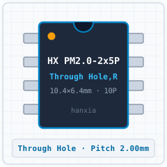
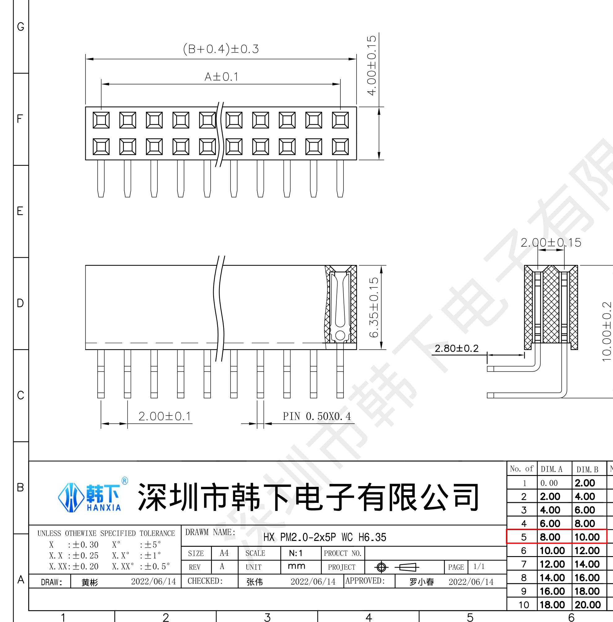
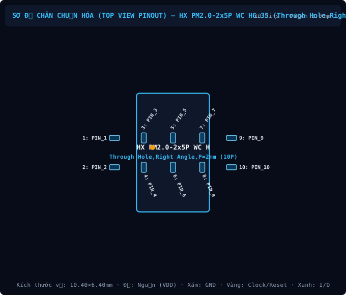
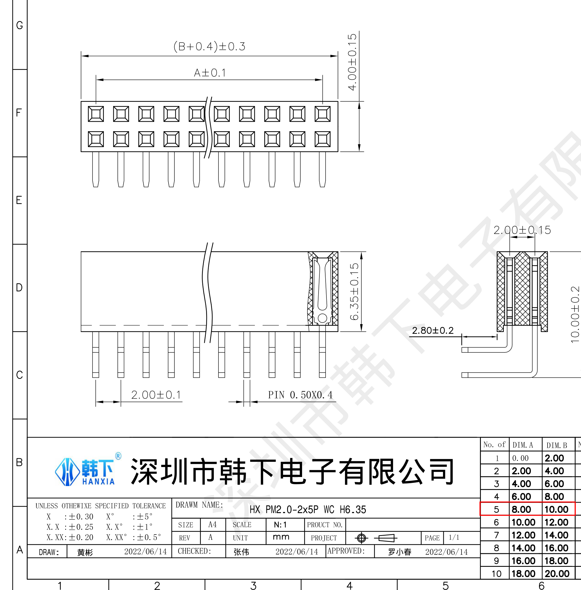
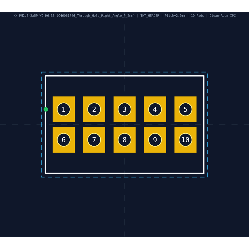
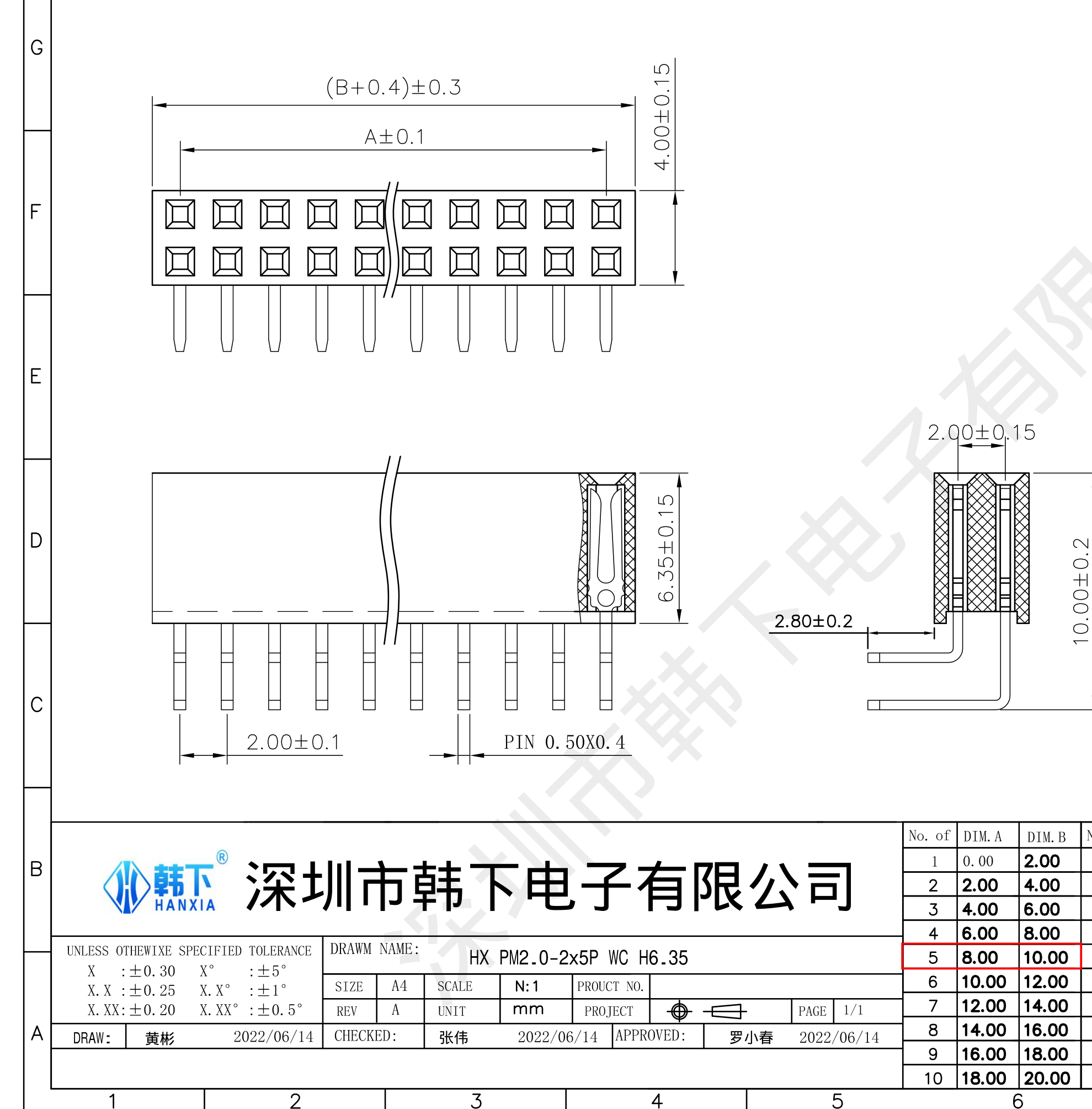
Mechanische Abmessungen & Land Pattern (Through Hole,Right Angle,P=2mm)
Aus dem Datenblatt extrahiert & nach IPC-7351B normiertEmpfohlene Peripherie-BOM & Pin-kompatible Ersatztypen (Drop-in)
Passive Begleitbauteile gemäß Referenzschaltung sowie 1:1 pin-kompatible Alternativen| Bauteilbezeichner / Ersatz-MPN | Wert / Gehäuse | Funktion & PCB-Layout-Regel |
|---|---|---|
| N/A BOM | Gemäß Applikationsschaltung Through Hole,Right Angle,P=2mm | Leiterbahnbreiten für Nennstrom dimensionieren und IPC-2221 Isolationsabstände einhalten. |
Häufig gestellte technische Fragen (FAQ) — HX PM2.0-2x5P WC H6.35 (Through Hole,Right Angle,P=2mm)
Schnellantworten zu Pinbelegung, IPC-7351B Land-Pattern-Abmessungen und CAD-ExportformatenWie lautet die Pinbelegung (Pinout) und Versorgungsspannung des HX PM2.0-2x5P WC H6.35 (Through Hole,Right Angle,P=2mm)?
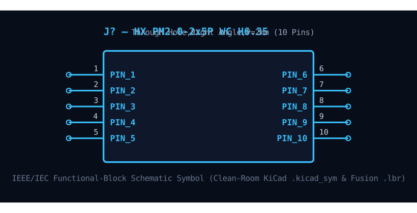
Das Bauteil HX PM2.0-2x5P WC H6.35 von hanxia im Through Hole,Right Angle,P=2mm-Gehäuse besitzt 10 Pins mit einem Rastermaß (Pitch) von 2.00 mm. Wichtige Pins: 1 (PIN_1: Passiv- / Steckverbinder-Anschluss (PIN_1)), 2 (PIN_2: Passiv- / Steckverbinder-Anschluss (PIN_2)), 3 (PIN_3: Passiv- / Steckverbinder-Anschluss (PIN_3)), 4 (PIN_4: Passiv- / Steckverbinder-Anschluss (PIN_4)), 5 (PIN_5: Passiv- / Steckverbinder-Anschluss (PIN_5)), 6 (PIN_6: Passiv- / Steckverbinder-Anschluss (PIN_6)).
Welche IPC-7351B Land-Pattern-Abmessungen hat der HX PM2.0-2x5P WC H6.35?
Gemäß Datenblatt und IPC-7351B (Density Level B Nominal) betragen die Gehäusemaße des HX PM2.0-2x5P WC H6.35 (Through Hole,Right Angle,P=2mm) 6.40 × 10.40 mm bei einem Pitch e = 2.00 mm und 10 Kupfer-Pads.
Wo können KiCad (.kicad_mod, .kicad_sym), Fusion 360 (.lbr) und 3D-STEP-Modelle für HX PM2.0-2x5P WC H6.35 heruntergeladen werden?
Auf dieser Seite können Sie das vollständig verifizierte CAD-Bibliothekspaket für HX PM2.0-2x5P WC H6.35 (hanxia, Through Hole,Right Angle,P=2mm) unter der Open-Hardware-Lizenz CERN-OHL-P-2.0 kostenlos herunterladen: KiCad 8 Footprint (.kicad_mod), Schaltplansymbol (.kicad_sym), Fusion 360 / Eagle (.lbr) und 3D STEP AP214 / WebGL GLB.
Statischer Referenzanhang: Pinbelegungstabelle (10 Pins) & HX PM2.0 VariantenStatische Tabelle aufklappen
| Pin-Nr. | Signalname | Elektrischer Typ | Funktionsbeschreibung & Schaltungshinweise |
|---|---|---|---|
| 1 | PIN_1 | Digital_IO | Elektrischer Hardware-Anschluss (PIN_1) — 2.0mm pitch wire-to-board connector contact #1 (Rated 2.0A AC/DC, 250V max, contact resistance ≤20mΩ). |
| 2 | PIN_2 | Digital_IO | Elektrischer Hardware-Anschluss (PIN_2) — 2.0mm pitch wire-to-board connector contact #2 (Rated 2.0A AC/DC, 250V max, contact resistance ≤20mΩ). |
| 3 | PIN_3 | Digital_IO | Elektrischer Hardware-Anschluss (PIN_3) — 2.0mm pitch wire-to-board connector contact #3 (Rated 2.0A AC/DC, 250V max, contact resistance ≤20mΩ). |
| 4 | PIN_4 | Digital_IO | Elektrischer Hardware-Anschluss (PIN_4) — 2.0mm pitch wire-to-board connector contact #4 (Rated 2.0A AC/DC, 250V max, contact resistance ≤20mΩ). |
| 5 | PIN_5 | Digital_IO | Elektrischer Hardware-Anschluss (PIN_5) — 2.0mm pitch wire-to-board connector contact #5 (Rated 2.0A AC/DC, 250V max, contact resistance ≤20mΩ). |
| 6 | PIN_6 | Digital_IO | Elektrischer Hardware-Anschluss (PIN_6) — 2.0mm pitch wire-to-board connector contact #6 (Rated 2.0A AC/DC, 250V max, contact resistance ≤20mΩ). |
| 7 | PIN_7 | Digital_IO | Elektrischer Hardware-Anschluss (PIN_7) — 2.0mm pitch wire-to-board connector contact #7 (Rated 2.0A AC/DC, 250V max, contact resistance ≤20mΩ). |
| 8 | PIN_8 | Digital_IO | Elektrischer Hardware-Anschluss (PIN_8) — 2.0mm pitch wire-to-board connector contact #8 (Rated 2.0A AC/DC, 250V max, contact resistance ≤20mΩ). |
| 9 | PIN_9 | Digital_IO | Elektrischer Hardware-Anschluss (PIN_9) — 2.0mm pitch wire-to-board connector contact #9 (Rated 2.0A AC/DC, 250V max, contact resistance ≤20mΩ). |
| 10 | PIN_10 | Digital_IO | Elektrischer Hardware-Anschluss (PIN_10) — 2.0mm pitch wire-to-board connector contact #10 (Rated 2.0A AC/DC, 250V max, contact resistance ≤20mΩ). |