
LQFP-64(10x10) · 64P
IPC-7351B
64P10.0×10.0×1.60mmP=0.5mm
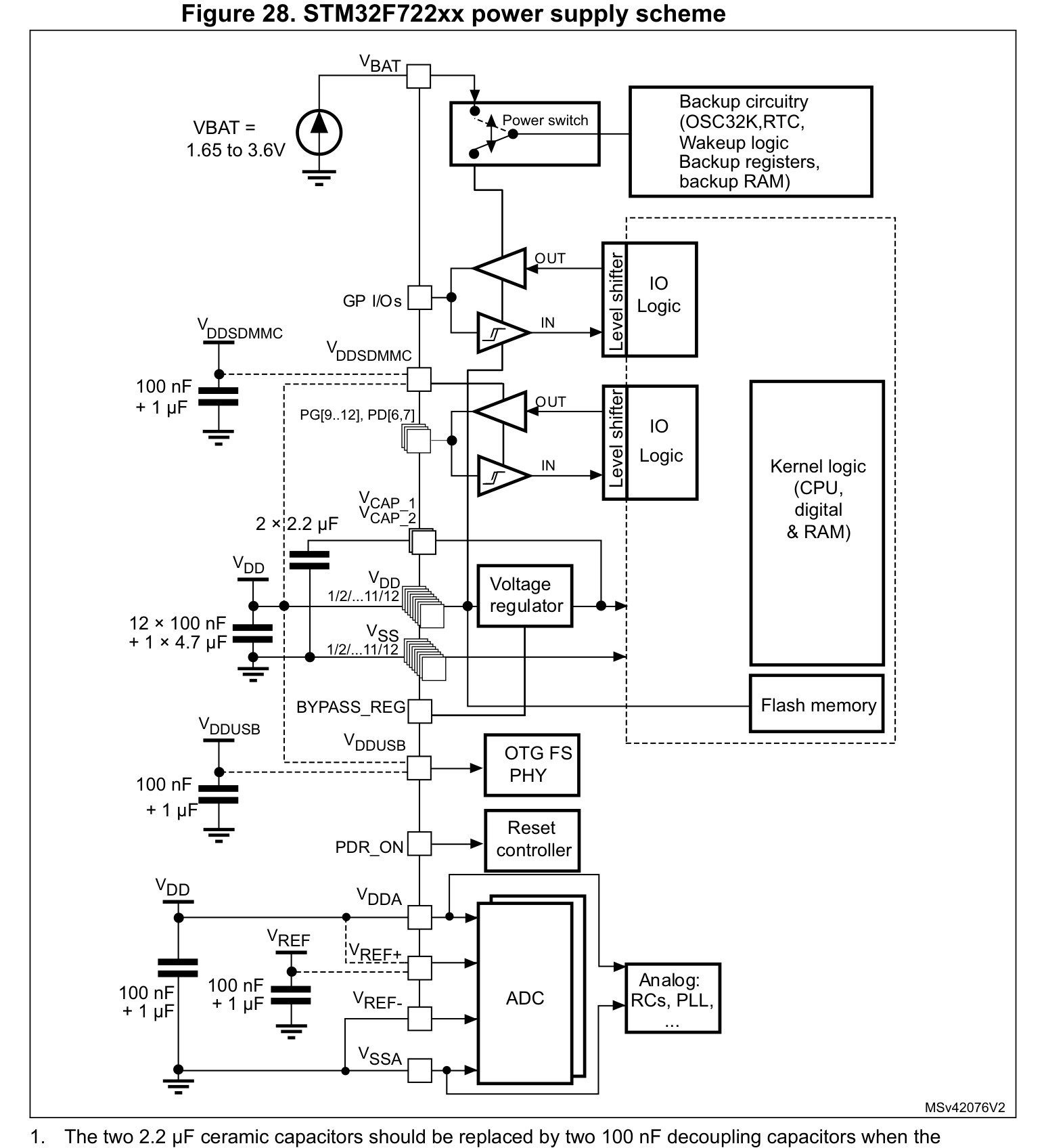
STM32F722 / STM32F723 (LQFP-64(10x10))
| Pin | Symbol | Typ | Funktionsbeschreibung (DE) |
|---|---|---|---|
| 1 | VBAT | Power | Versorgungsspannungseingang (VBAT — 3.3V VDD (Max 4.0V)) |
| 2 | PC13 | I/O | Multiplex-I/O- & Peripherie-Pin PC13 (RTC/CLK) |
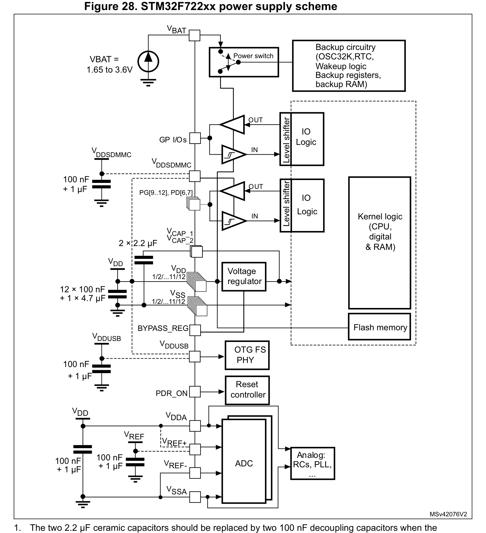
| 3 | 3V3 | Power | 3.3V Main Power Supply Rail (3.0V ~ 3.6V) |
| 4 | NC | NC | No Connect (Leave Floating) |
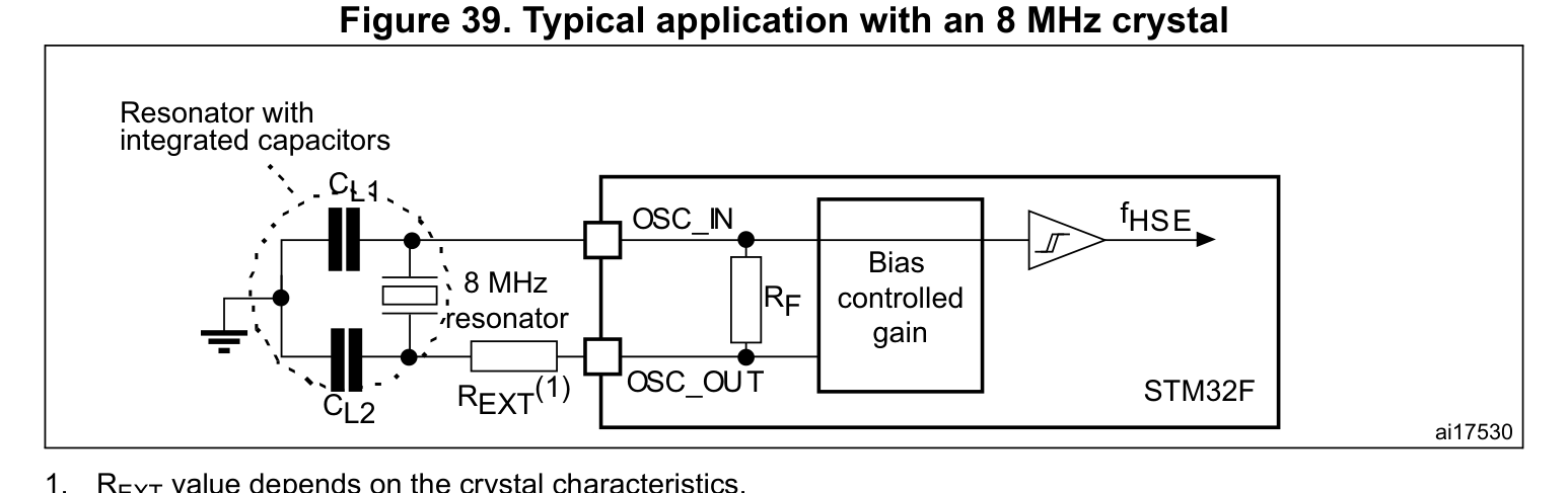
| 5 | PH0OSC IN -_ | I/O | Multiplex-I/O- & Peripherie-Pin PH0OSC IN -_ (RTC/CLK) |
| 6 | PH1OSC OUT -_ | I/O | Multiplex-I/O- & Peripherie-Pin PH1OSC OUT -_ (RTC/CLK) |
| 7 | NRST | I | Systemfreigabe & Hardware-Reset (NRST) |
| 8 | PC0 | I/O | Multiplex-I/O- & Peripherie-Pin PC0 (ADC) |
| 9 | PC1 | I/O | Multiplex-I/O- & Peripherie-Pin PC1 (SPI, I2C, ADC, RTC/CLK) |
| 10 | PC2 | I/O | Multiplex-I/O- & Peripherie-Pin PC2 (SPI, ADC) |
| 11 | PC3 | I/O | Multiplex-I/O- & Peripherie-Pin PC3 (SPI, ADC) |
| 12 | VSSA | GND | Masseanschluss (VSSA) |
| 13 | VREF+ | Analog | Multiplex-I/O- & Peripherie-Pin VREF+ (General) |
| 14 | PA0WKUP - | I/O | Multiplex-I/O- & Peripherie-Pin PA0WKUP - (UART, ADC, PWM) |
| 15 | PA1 | I/O | Multiplex-I/O- & Peripherie-Pin PA1 (UART, ADC, PWM) |
| 16 | PA2 | I/O | Multiplex-I/O- & Peripherie-Pin PA2 (SPI, ADC, PWM) |
| 17 | PA3 | I/O | Multiplex-I/O- & Peripherie-Pin PA3 (ADC, PWM) |
| 18 | VSS | GND | Masseanschluss (VSS) |
| 19 | VDD | Power | Versorgungsspannungseingang (VDD — 3.3V VDD (Max 4.0V)) |
| 20 | PA4 | I/O | Multiplex-I/O- & Peripherie-Pin PA4 (UART, SPI, ADC, DAC) |
| 21 | PA5 | I/O | Multiplex-I/O- & Peripherie-Pin PA5 (SPI, ADC, DAC, PWM) |
| 22 | PA6 | I/O | Multiplex-I/O- & Peripherie-Pin PA6 (ADC) |
| 23 | PA7 | I/O | Multiplex-I/O- & Peripherie-Pin PA7 (SPI, ADC, PWM) |
| 24 | PC4 | I/O | Multiplex-I/O- & Peripherie-Pin PC4 (ADC) |
| 25 | PB0 | I/O | Multiplex-I/O- & Peripherie-Pin PB0 (ADC, PWM) |
| 26 | PB1 | I/O | Multiplex-I/O- & Peripherie-Pin PB1 (ADC, PWM) |
| 27 | PB2 | I/O | Multiplex-I/O- & Peripherie-Pin PB2 (SPI, I2C) |
| 28 | PB10 | I/O | Multiplex-I/O- & Peripherie-Pin PB10 (UART, SPI, PWM) |
| 29 | PB11 | I/O | Multiplex-I/O- & Peripherie-Pin PB11 (UART, PWM) |
| 30 | VCAP_1 | I/O | Multiplex-I/O- & Peripherie-Pin VCAP_1 (General) |
| 31 | VSS | GND | Masseanschluss (VSS) |
| 32 | VDD | Power | Versorgungsspannungseingang (VDD — 3.3V VDD (Max 4.0V)) |
| 33 | PB12 | I/O | Multiplex-I/O- & Peripherie-Pin PB12 (UART, SPI) |
| 34 | PB13 | I/O | Multiplex-I/O- & Peripherie-Pin PB13 (UART, SPI, PWM) |
| 35 | PB14 | I/O | Multiplex-I/O- & Peripherie-Pin PB14 (SPI, PWM) |
| 36 | PB15 | I/O | Multiplex-I/O- & Peripherie-Pin PB15 (SPI, PWM, RTC/CLK) |
| 37 | PC6 | I/O | Multiplex-I/O- & Peripherie-Pin PC6 (PWM) |
| 38 | PC7 | I/O | Multiplex-I/O- & Peripherie-Pin PC7 (PWM) |
| 39 | PC8 | I/O | Multiplex-I/O- & Peripherie-Pin PC8 (UART, PWM) |
| 40 | PC9 | I/O | Multiplex-I/O- & Peripherie-Pin PC9 (UART, I2C, RTC/CLK) |
| 41 | PA8 | I/O | Multiplex-I/O- & Peripherie-Pin PA8 (I2C, RTC/CLK) |
| 42 | PA9 | I/O | Multiplex-I/O- & Peripherie-Pin PA9 (UART, SPI, PWM) |
| 43 | PA10 | I/O | Multiplex-I/O- & Peripherie-Pin PA10 (PWM) |
| 44 | PA11 | I/O | Multiplex-I/O- & Peripherie-Pin PA11 (PWM, CAN) |
| 45 | PA12 | I/O | Multiplex-I/O- & Peripherie-Pin PA12 (General) |
| 46 | PA13(JTMS - SWDIO) | I/O | Multiplex-I/O- & Peripherie-Pin PA13(JTMS - SWDIO) (SWD/JTAG) |
| 47 | VSS | GND | Masseanschluss (VSS) |
| 48 | VDD | Power | Versorgungsspannungseingang (VDD — 3.3V VDD (Max 4.0V)) |
| 49 | PA14(JTCK - SWCLK) | I/O | Multiplex-I/O- & Peripherie-Pin PA14(JTCK - SWCLK) (SWD/JTAG) |
| 50 | PA15(JTDI) | I/O | Multiplex-I/O- & Peripherie-Pin PA15(JTDI) (UART, SPI, SWD/JTAG) |
| 51 | PC10 | I/O | Multiplex-I/O- & Peripherie-Pin PC10 (UART, SPI) |
| 52 | PC11 | I/O | Multiplex-I/O- & Peripherie-Pin PC11 (UART, SPI) |
| 53 | PC12 | I/O | Multiplex-I/O- & Peripherie-Pin PC12 (UART, SPI) |
| 54 | PD2 | I/O | Multiplex-I/O- & Peripherie-Pin PD2 (UART) |
| 55 | PB3(JTDO/TRA CESWO) | I/O | Multiplex-I/O- & Peripherie-Pin PB3(JTDO/TRA CESWO) (SPI, SWD/JTAG) |
| 56 | PB4(NJTRST) | I/O | Multiplex-I/O- & Peripherie-Pin PB4(NJTRST) (SPI, SWD/JTAG) |
| 57 | PB5 | I/O | Multiplex-I/O- & Peripherie-Pin PB5 (SPI, PWM) |
| 58 | PB6 | I/O | Multiplex-I/O- & Peripherie-Pin PB6 (UART, PWM) |
| 59 | PB7 | I/O | Multiplex-I/O- & Peripherie-Pin PB7 (UART, PWM) |
| 60 | BOOT | I/O | Multiplex-I/O- & Peripherie-Pin BOOT (General) |
| 61 | PB8 | I/O | Multiplex-I/O- & Peripherie-Pin PB8 (I2C, PWM) |
| 62 | PB9 | I/O | Multiplex-I/O- & Peripherie-Pin PB9 (SPI, I2C, PWM, CAN) |
| 63 | VSS | GND | Masseanschluss (VSS) |
| 64 | VDD | Power | Versorgungsspannungseingang (VDD — 3.3V VDD (Max 4.0V)) |
| 65 | PF15 | I/O | Multiplex-I/O- & Peripherie-Pin PF15 (General) |
| 66 | PG0 | I/O | Multiplex-I/O- & Peripherie-Pin PG0 (General) |
| 67 | PG1 | I/O | Multiplex-I/O- & Peripherie-Pin PG1 (General) |
| 68 | PE7 | I/O | Multiplex-I/O- & Peripherie-Pin PE7 (General) |
| 69 | PE8 | I/O | Multiplex-I/O- & Peripherie-Pin PE8 (General) |
| 70 | PE9 | I/O | Multiplex-I/O- & Peripherie-Pin PE9 (General) |
| 71 | VSS | GND | Masseanschluss (VSS) |
| 72 | VDD | Power | Versorgungsspannungseingang (VDD — 3.3V VDD (Max 4.0V)) |
| 73 | PE10 | I/O | Multiplex-I/O- & Peripherie-Pin PE10 (General) |
| 74 | PE11 | I/O | Multiplex-I/O- & Peripherie-Pin PE11 (General) |
| 75 | PE12 | I/O | Multiplex-I/O- & Peripherie-Pin PE12 (General) |
| 76 | PE13 | I/O | Multiplex-I/O- & Peripherie-Pin PE13 (General) |
| 77 | PE14 | I/O | Multiplex-I/O- & Peripherie-Pin PE14 (General) |
| 78 | PE15 | I/O | Multiplex-I/O- & Peripherie-Pin PE15 (General) |
| 79 | PB10 | I/O | Multiplex-I/O- & Peripherie-Pin PB10 (General) |
| 80 | PB11 | I/O | Multiplex-I/O- & Peripherie-Pin PB11 (General) |
| 81 | VCAP_1 | I/O | Multiplex-I/O- & Peripherie-Pin VCAP_1 (General) |
| 82 | VDD | Power | Versorgungsspannungseingang (VDD — 3.3V VDD (Max 4.0V)) |
| 83 | PH6 | I/O | Multiplex-I/O- & Peripherie-Pin PH6 (General) |
| 84 | PH7 | I/O | Multiplex-I/O- & Peripherie-Pin PH7 (General) |
| 85 | PH8 | I/O | Multiplex-I/O- & Peripherie-Pin PH8 (General) |
| 86 | PH9 | I/O | Multiplex-I/O- & Peripherie-Pin PH9 (General) |
| 87 | PH10 | I/O | Multiplex-I/O- & Peripherie-Pin PH10 (General) |
| 88 | PH11 | I/O | Multiplex-I/O- & Peripherie-Pin PH11 (General) |
| 89 | PH12 | I/O | Multiplex-I/O- & Peripherie-Pin PH12 (General) |
| 90 | VSS | GND | Masseanschluss (VSS) |
| 91 | VDD | Power | Versorgungsspannungseingang (VDD — 3.3V VDD (Max 4.0V)) |
| 92 | PB12 | I/O | Multiplex-I/O- & Peripherie-Pin PB12 (General) |
| 93 | PB13 | I/O | Multiplex-I/O- & Peripherie-Pin PB13 (General) |
| 94 | PB14 | I/O | Multiplex-I/O- & Peripherie-Pin PB14 (General) |
| 95 | PB15 | I/O | Multiplex-I/O- & Peripherie-Pin PB15 (General) |
| 96 | PD8 | I/O | Multiplex-I/O- & Peripherie-Pin PD8 (General) |
| 97 | PD9 | I/O | Multiplex-I/O- & Peripherie-Pin PD9 (General) |
| 98 | PD10 | I/O | Multiplex-I/O- & Peripherie-Pin PD10 (General) |
| 99 | PD11 | I/O | Multiplex-I/O- & Peripherie-Pin PD11 (General) |
| 100 | PD12 | I/O | Multiplex-I/O- & Peripherie-Pin PD12 (General) |
| 101 | PD13 | I/O | Multiplex-I/O- & Peripherie-Pin PD13 (General) |
| 102 | VSS | GND | Masseanschluss (VSS) |
| 103 | VDD | Power | Versorgungsspannungseingang (VDD — 3.3V VDD (Max 4.0V)) |
| 104 | PD14 | I/O | Multiplex-I/O- & Peripherie-Pin PD14 (General) |
| 105 | PD15 | I/O | Multiplex-I/O- & Peripherie-Pin PD15 (General) |
| 106 | PG2 | I/O | Multiplex-I/O- & Peripherie-Pin PG2 (General) |
| 107 | PG3 | I/O | Multiplex-I/O- & Peripherie-Pin PG3 (General) |
| 108 | PG4 | I/O | Multiplex-I/O- & Peripherie-Pin PG4 (General) |
| 109 | PG5 | I/O | Multiplex-I/O- & Peripherie-Pin PG5 (General) |
| 110 | PG6 | I/O | Multiplex-I/O- & Peripherie-Pin PG6 (General) |
| 111 | PG7 | I/O | Multiplex-I/O- & Peripherie-Pin PG7 (General) |
| 112 | PG8 | I/O | Multiplex-I/O- & Peripherie-Pin PG8 (General) |
| 113 | VSS | GND | Masseanschluss (VSS) |
| 114 | VDDUSB | Power | Versorgungsspannungseingang (VDDUSB — 3.3V VDD (Max 4.0V)) |
| 115 | PC6 | I/O | Multiplex-I/O- & Peripherie-Pin PC6 (General) |
| 116 | PC7 | I/O | Multiplex-I/O- & Peripherie-Pin PC7 (General) |
| 117 | PC8 | I/O | Multiplex-I/O- & Peripherie-Pin PC8 (General) |
| 118 | PC9 | I/O | Multiplex-I/O- & Peripherie-Pin PC9 (General) |
| 119 | PA8 | I/O | Multiplex-I/O- & Peripherie-Pin PA8 (General) |
| 120 | PA9 | I/O | Multiplex-I/O- & Peripherie-Pin PA9 (General) |
| 121 | PA10 | I/O | Multiplex-I/O- & Peripherie-Pin PA10 (General) |
| 122 | PA11 | I/O | Multiplex-I/O- & Peripherie-Pin PA11 (General) |
| 123 | PA12 | I/O | Multiplex-I/O- & Peripherie-Pin PA12 (General) |
| 124 | PA13 | I/O | Multiplex-I/O- & Peripherie-Pin PA13 (General) |
| 125 | PG10 | I/O | Multiplex-I/O- & Peripherie-Pin PG10 (General) |
| 126 | PG11 | I/O | Multiplex-I/O- & Peripherie-Pin PG11 (General) |
| 127 | PG12 | I/O | Multiplex-I/O- & Peripherie-Pin PG12 (General) |
| 128 | PG13 | I/O | Multiplex-I/O- & Peripherie-Pin PG13 (UART) |
| 129 | PG14 | I/O | Multiplex-I/O- & Peripherie-Pin PG14 (UART) |
| 130 | VSS | GND | Masseanschluss (VSS) |
| 131 | PI0 | I/O | Multiplex-I/O- & Peripherie-Pin PI0 (General) |
| 132 | PI1 | I/O | Multiplex-I/O- & Peripherie-Pin PI1 (General) |
| 133 | PI2 | I/O | Multiplex-I/O- & Peripherie-Pin PI2 (General) |
| 134 | PI3 | I/O | Multiplex-I/O- & Peripherie-Pin PI3 (General) |
| 135 | VSS | GND | Masseanschluss (VSS) |
| 136 | VDD | Power | Versorgungsspannungseingang (VDD — 3.3V VDD (Max 4.0V)) |
| 137 | PA14 | I/O | Multiplex-I/O- & Peripherie-Pin PA14 (General) |
| 138 | PA15 | I/O | Multiplex-I/O- & Peripherie-Pin PA15 (General) |
| 139 | PC10 | I/O | Multiplex-I/O- & Peripherie-Pin PC10 (General) |
| 140 | PC11 | I/O | Multiplex-I/O- & Peripherie-Pin PC11 (General) |
| 141 | PC12 | I/O | Multiplex-I/O- & Peripherie-Pin PC12 (General) |
| 142 | PD0 | I/O | Multiplex-I/O- & Peripherie-Pin PD0 (General) |
| 143 | PD1 | I/O | Multiplex-I/O- & Peripherie-Pin PD1 (General) |
| 144 | PD2 | I/O | Multiplex-I/O- & Peripherie-Pin PD2 (General) |
| 145 | PD3 | I/O | Multiplex-I/O- & Peripherie-Pin PD3 (General) |
| 146 | PD4 | I/O | Multiplex-I/O- & Peripherie-Pin PD4 (General) |
| 147 | PD5 | I/O | Multiplex-I/O- & Peripherie-Pin PD5 (General) |
| 148 | VSS | GND | Masseanschluss (VSS) |
| 149 | VDDSDMMC | Power | Versorgungsspannungseingang (VDDSDMMC — 3.3V VDD (Max 4.0V)) |
| 150 | PD6 | I/O | Multiplex-I/O- & Peripherie-Pin PD6 (General) |
| 151 | PD7 | I/O | Multiplex-I/O- & Peripherie-Pin PD7 (General) |
| 152 | PG9 | I/O | Multiplex-I/O- & Peripherie-Pin PG9 (General) |
| 153 | PG10 | I/O | Multiplex-I/O- & Peripherie-Pin PG10 (General) |
| 154 | PG11 | I/O | Multiplex-I/O- & Peripherie-Pin PG11 (General) |
| 155 | PG12 | I/O | Multiplex-I/O- & Peripherie-Pin PG12 (General) |
| 156 | PG13 | I/O | Multiplex-I/O- & Peripherie-Pin PG13 (General) |
| 157 | PG14 | I/O | Multiplex-I/O- & Peripherie-Pin PG14 (General) |
| 158 | VSS | GND | Masseanschluss (VSS) |
| 159 | VDD | Power | Versorgungsspannungseingang (VDD — 3.3V VDD (Max 4.0V)) |
| 160 | PG15 | I/O | Multiplex-I/O- & Peripherie-Pin PG15 (General) |
| 161 | PB3 | I/O | Multiplex-I/O- & Peripherie-Pin PB3 (General) |
| 162 | PB4 | I/O | Multiplex-I/O- & Peripherie-Pin PB4 (General) |
| 163 | PB5 | I/O | Multiplex-I/O- & Peripherie-Pin PB5 (General) |
| 164 | PB6 | I/O | Multiplex-I/O- & Peripherie-Pin PB6 (General) |
| 165 | PB7 | I/O | Multiplex-I/O- & Peripherie-Pin PB7 (General) |
| 166 | BOOT0 | I | Reiner Eingangs-Pin BOOT0 (General) |
| 167 | PB8 | I/O | Multiplex-I/O- & Peripherie-Pin PB8 (General) |
| 168 | PB9 | I/O | Multiplex-I/O- & Peripherie-Pin PB9 (General) |
| 169 | PE0 | I/O | Multiplex-I/O- & Peripherie-Pin PE0 (General) |
| 170 | PE1 | I/O | Multiplex-I/O- & Peripherie-Pin PE1 (General) |
| 171 | PDR_ON | I/O | Multiplex-I/O- & Peripherie-Pin PDR_ON (General) |
| 172 | VDD | Power | Versorgungsspannungseingang (VDD — 3.3V VDD (Max 4.0V)) |
| 173 | PI4 | I/O | Multiplex-I/O- & Peripherie-Pin PI4 (General) |
| 174 | PI5 | I/O | Multiplex-I/O- & Peripherie-Pin PI5 (General) |
| 175 | PI6 | I/O | Multiplex-I/O- & Peripherie-Pin PI6 (General) |
| 176 | PI7 | I/O | Multiplex-I/O- & Peripherie-Pin PI7 (General) |
STM32F722 / STM32F723 (LQFP-64(10x10))
STM32F722 / STM32F723 (LQFP-64(10x10))
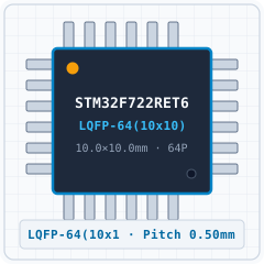
STM32F722 / STM32F723 (LQFP-64(10x10))
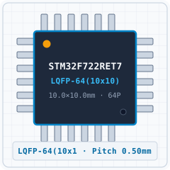
STM32F722 / STM32F723 (LQFP-64(10x10))
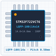
STM32F722 / STM32F723 (LQFP-100(14x14))
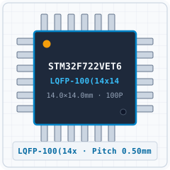
STM32F722 / STM32F723 (LQFP-100(14x14))
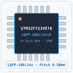
STM32F722 / STM32F723 (LQFP-100(14x14))
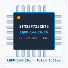
STM32F722 / STM32F723 (LQFP-144(20x20))
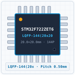
STM32F722 / STM32F723 (LQFP-144(20x20))
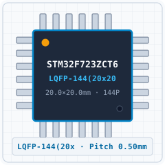
STM32F722 / STM32F723 (LQFP-144(20x20))

STM32F722 / STM32F723 (LQFP-144(20x20))
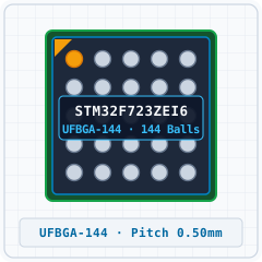
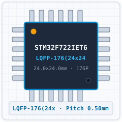
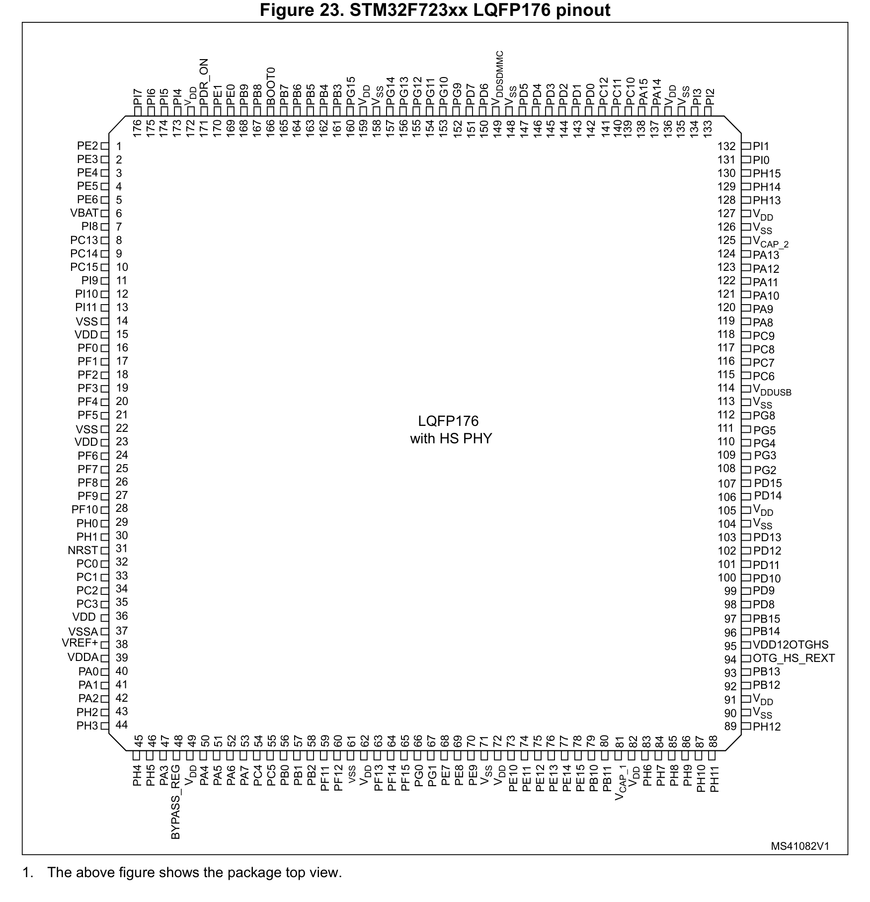
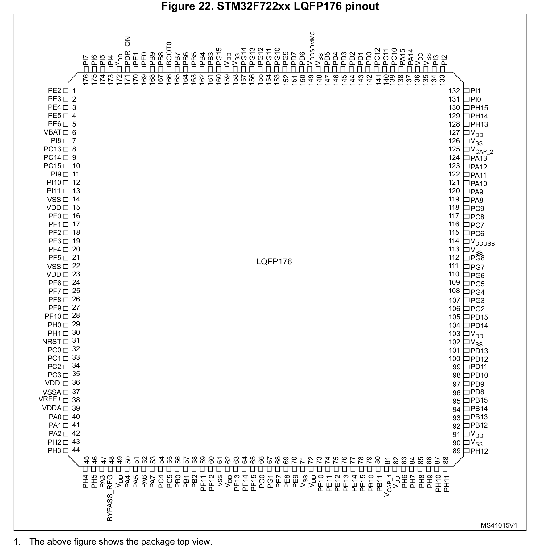
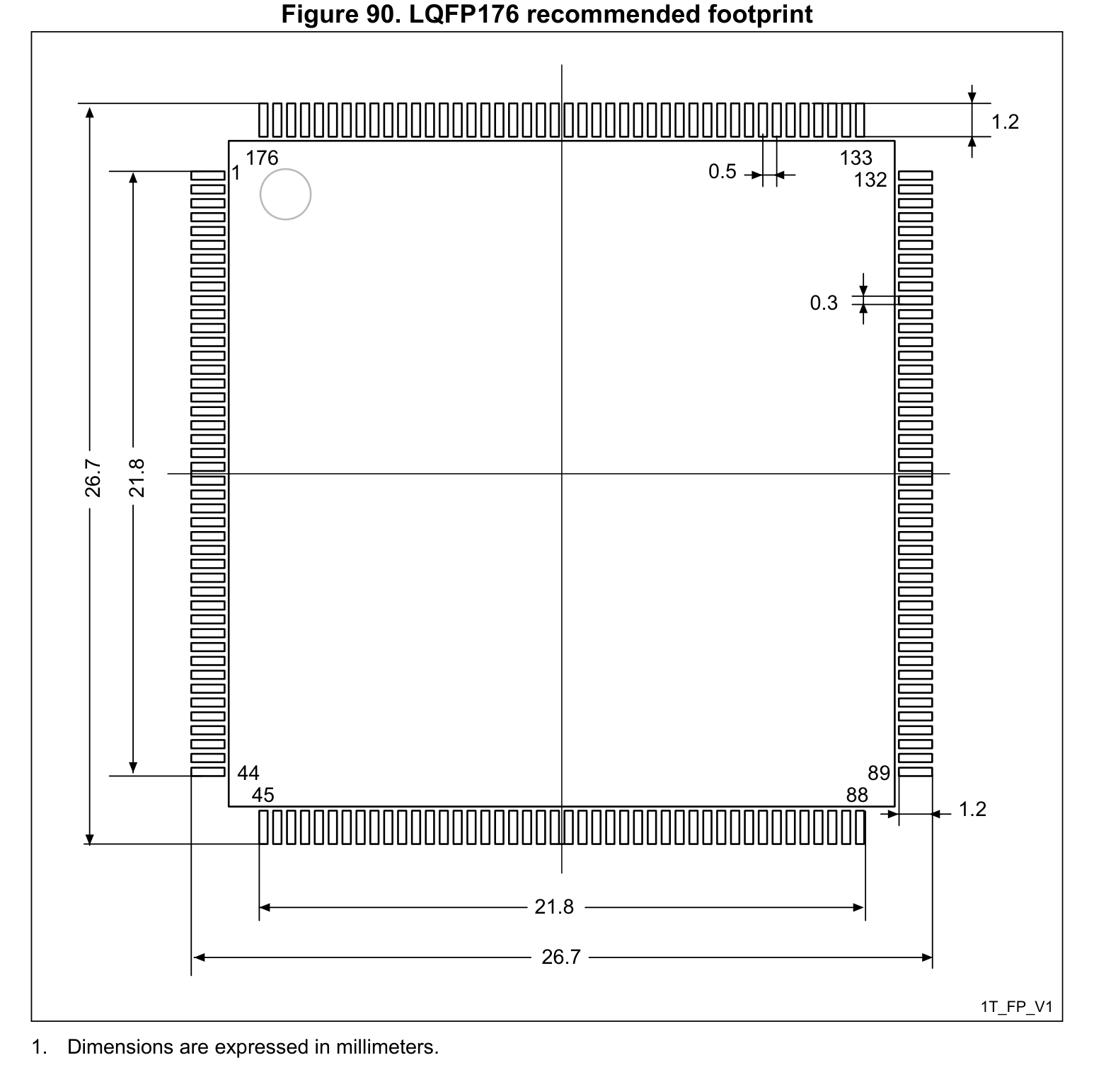
STM32F722 / STM32F723 (LQFP-176(24x24))
STM32F722 / STM32F723 (LQFP-176(24x24))
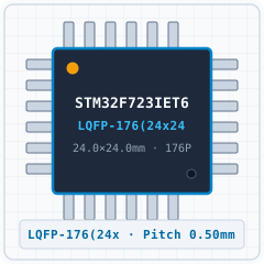
STM32F722 / STM32F723 (LQFP-176(24x24))
| Bauteilbezeichner / Ersatz-MPN | Wert / Gehäuse | Funktion & PCB-Layout-Regel |
|---|---|---|
| N/A BOM | Per application circuit LQFP-176(24x24) | Leiterbahnbreiten für Nennstrom dimensionieren und IPC-2221 Isolationsabstände einhalten. |
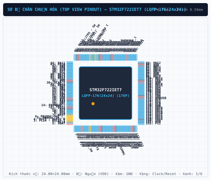
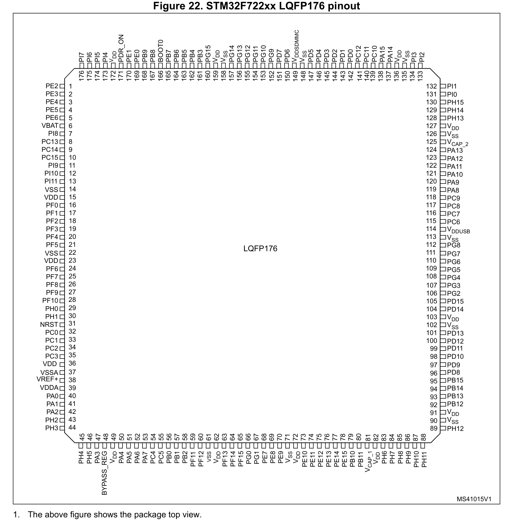
Das Bauteil STM32F722IET7 von ST im LQFP-176(24x24)-Gehäuse besitzt 176 Pins mit einem Rastermaß (Pitch) von 0.50 mm und einem Betriebsspannungsbereich VCC von 1.7 V to 3.6 V. Wichtige Pins: 1 (VBAT: Versorgungsspannungseingang (VBAT — 3.3V VDD (Max 4.0V))), 2 (PC13: Multiplex-I/O- & Peripherie-Pin PC13 (RTC/CLK)), 3 (3V3: 3.3V Main Power Supply Rail (3.0V ~ 3.6V)), 4 (NC: No Connect (Leave Floating)), 5 (PH0OSC IN -_: Multiplex-I/O- & Peripherie-Pin PH0OSC IN -_ (RTC/CLK)), 6 (PH1OSC OUT -_: Multiplex-I/O- & Peripherie-Pin PH1OSC OUT -_ (RTC/CLK)).
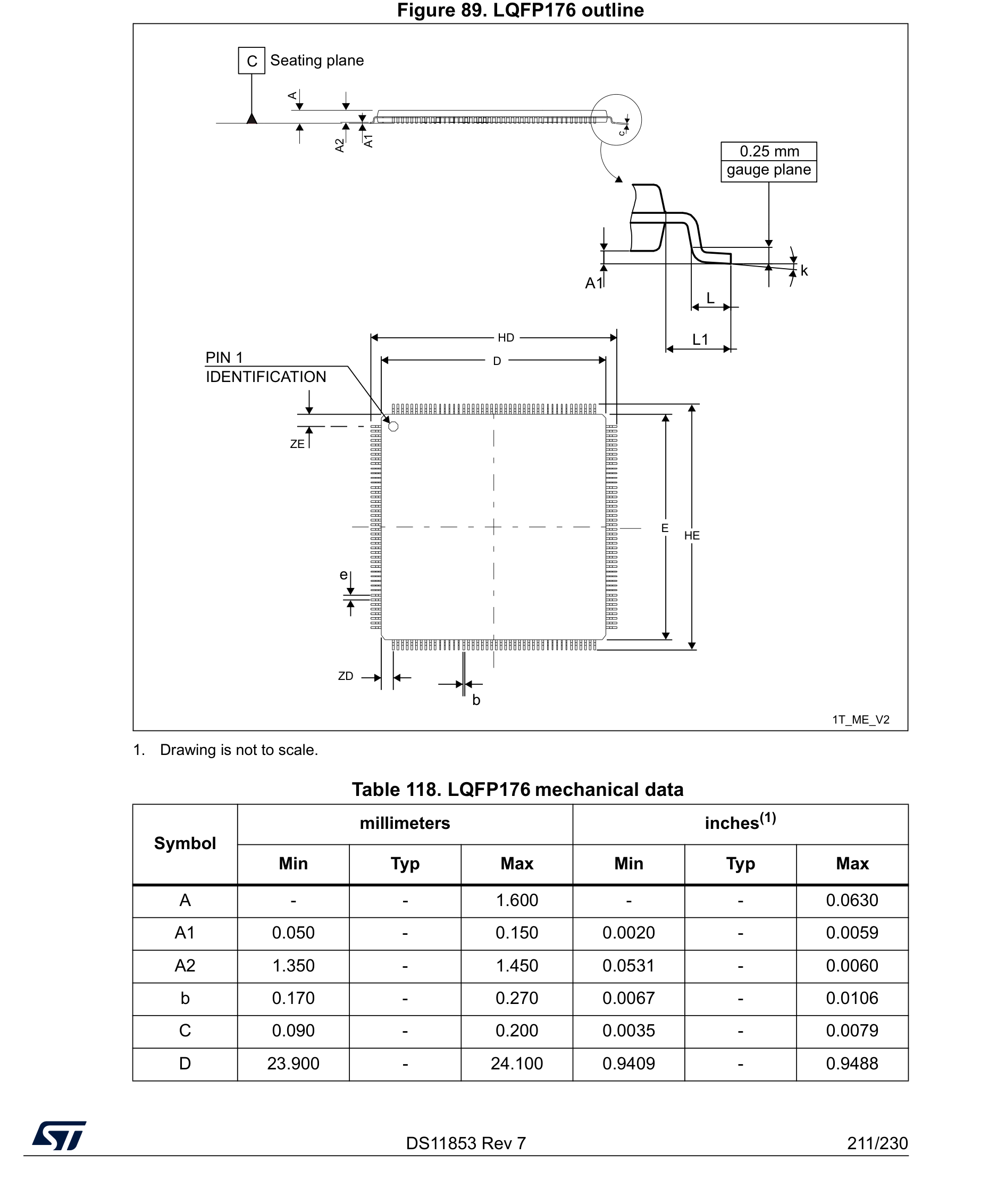
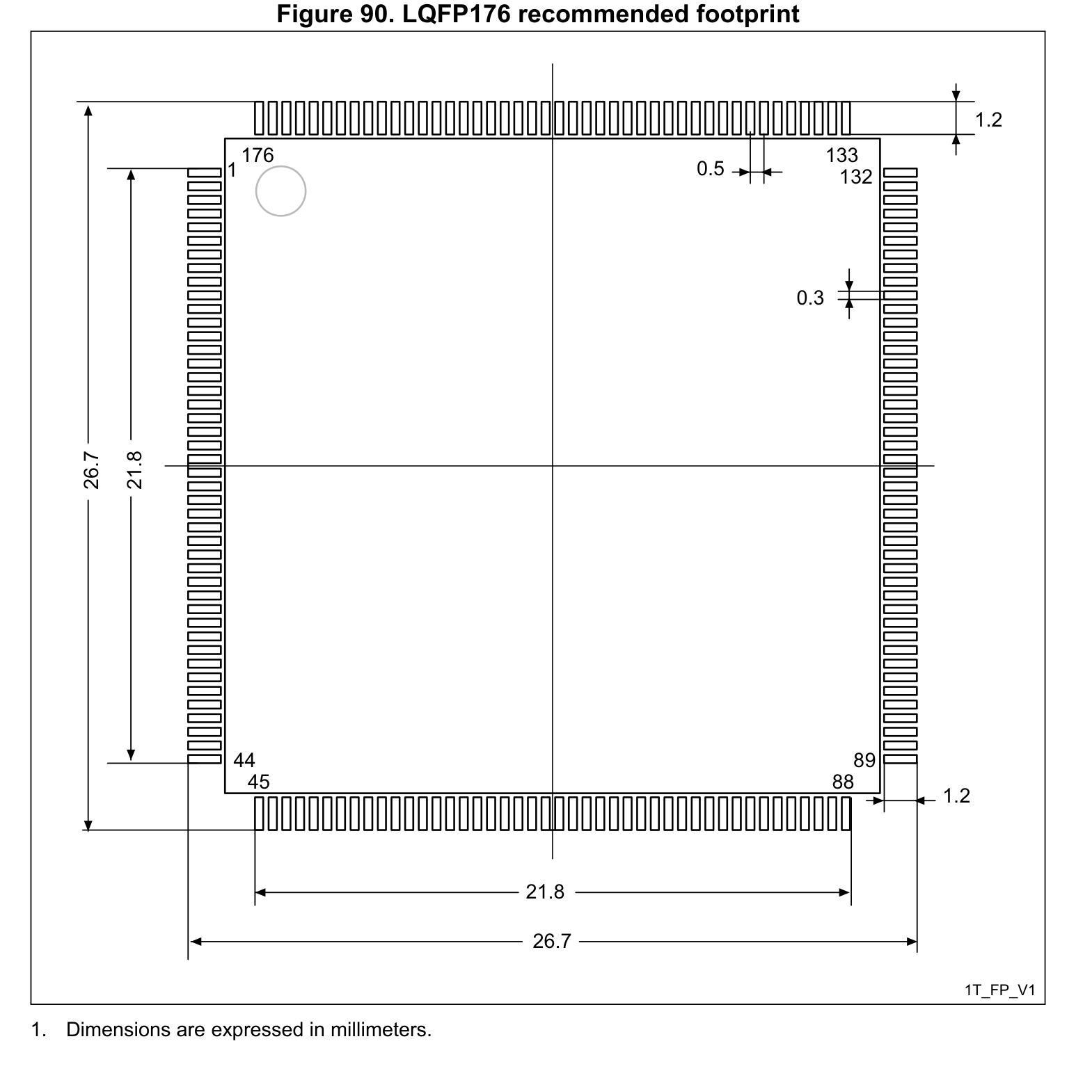
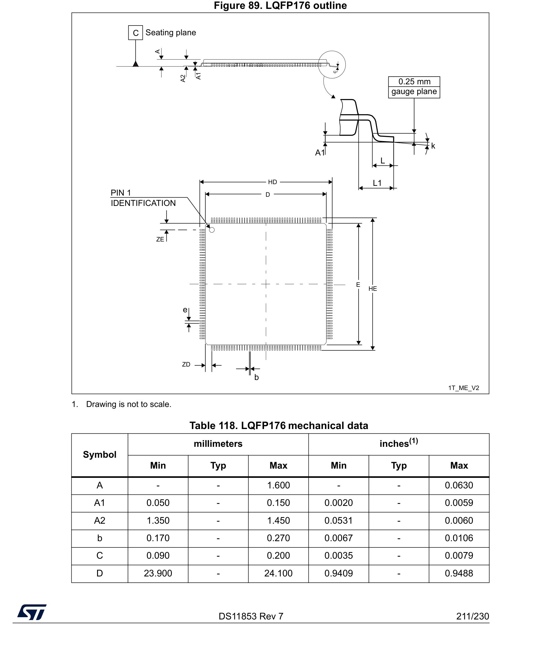
Gemäß Datenblatt und IPC-7351B (Density Level B Nominal) betragen die Gehäusemaße des STM32F722IET7 (LQFP-176(24x24)) 24.00 × 24.00 mm bei einem Pitch e = 0.50 mm und 176 Kupfer-Pads.
Auf dieser Seite können Sie das vollständig verifizierte CAD-Bibliothekspaket für STM32F722IET7 (ST, LQFP-176(24x24)) unter der Open-Hardware-Lizenz CERN-OHL-P-2.0 kostenlos herunterladen: KiCad 8 Footprint (.kicad_mod), Schaltplansymbol (.kicad_sym), Fusion 360 / Eagle (.lbr) und 3D STEP AP214 / WebGL GLB.
| Pin-Nr. | Signalname | Elektrischer Typ | Funktionsbeschreibung & Schaltungshinweise |
|---|---|---|---|
| 1 | VBAT | Power_In | Positiver Versorgungseingang (VBAT) im Spannungsbereich 3.3V VDD (Max 4.0V) (Max. 4.0V). |
| 2 | PC13 | Digital_IO | Signalanschluss PC13 (Richtung: I/O, Spannungsbereich: 3.3V VDD (5V-Tolerant FT)). Alternative Multiplex-Funktionen: PC13. Unterstützte Bus-Schnittstellen: RTC/CLK. |
| 3 | 3V3 | Power_In | 3.3V Main Power Supply Rail (3.0V ~ 3.6V) |
| 4 | NC | No_Connect | No Connect (Leave Floating) |
| 5 | PH0OSC IN -_ | Digital_IO | Signalanschluss PH0OSC IN -_ (Richtung: I/O, Spannungsbereich: 3.3V VDD (5V-Tolerant FT)). Alternative Multiplex-Funktionen: PH0OSC IN -_. Unterstützte Bus-Schnittstellen: RTC/CLK. |
| 6 | PH1OSC OUT -_ | Digital_IO | Signalanschluss PH1OSC OUT -_ (Richtung: I/O, Spannungsbereich: 3.3V VDD (5V-Tolerant FT)). Alternative Multiplex-Funktionen: PH1OSC OUT -_. Unterstützte Bus-Schnittstellen: RTC/CLK. |
| 7 | NRST | Digital_IO | Aktiv-niedriger Hardware-Reset-Anschluss (NRST): Low-Pegel setzt Prozessorkern und Peripherie zurück. |
| 8 | PC0 | Digital_IO | Signalanschluss PC0 (Richtung: I/O, Spannungsbereich: 3.3V VDD (5V-Tolerant FT)). Alternative Multiplex-Funktionen: PC0. Unterstützte Bus-Schnittstellen: ADC. |
| 9 | PC1 | Digital_IO | Signalanschluss PC1 (Richtung: I/O, Spannungsbereich: 3.3V VDD (5V-Tolerant FT)). Alternative Multiplex-Funktionen: SPI2_MOSI. Unterstützte Bus-Schnittstellen: SPI, I2C, ADC, RTC/CLK. |
| 10 | PC2 | Digital_IO | Signalanschluss PC2 (Richtung: I/O, Spannungsbereich: 3.3V VDD (5V-Tolerant FT)). Alternative Multiplex-Funktionen: SPI2_MISO. Unterstützte Bus-Schnittstellen: SPI, ADC. |
| 11 | PC3 | Digital_IO | Signalanschluss PC3 (Richtung: I/O, Spannungsbereich: 3.3V VDD (5V-Tolerant FT)). Alternative Multiplex-Funktionen: SPI2_MOSI. Unterstützte Bus-Schnittstellen: SPI, ADC. |
| 12 | VSSA | GND | Elektrischer 0V-Masserückführungsanschluss (VSSA) für Kernlogik, I/O-Treiber und Analogblöcke. |
| 13 | VREF+ | Analog | Signalanschluss VREF+ (Richtung: Analog, Spannungsbereich: 3.3V VDD (Max 4.0V)). Alternative Multiplex-Funktionen: VREF+. Unterstützte Bus-Schnittstellen: General. |
| 14 | PA0WKUP - | Digital_IO | Signalanschluss PA0WKUP - (Richtung: I/O, Spannungsbereich: 3.3V VDD (5V-Tolerant FT)). Alternative Multiplex-Funktionen: PA0WKUP -. Unterstützte Bus-Schnittstellen: UART, ADC, PWM. |
| 15 | PA1 | Digital_IO | Signalanschluss PA1 (Richtung: I/O, Spannungsbereich: 3.3V VDD (5V-Tolerant FT)). Alternative Multiplex-Funktionen: PA1. Unterstützte Bus-Schnittstellen: UART, ADC, PWM. |
| 16 | PA2 | Digital_IO | Signalanschluss PA2 (Richtung: I/O, Spannungsbereich: 3.3V VDD (5V-Tolerant FT)). Alternative Multiplex-Funktionen: PA2. Unterstützte Bus-Schnittstellen: SPI, ADC, PWM. |
| 17 | PA3 | Digital_IO | Signalanschluss PA3 (Richtung: I/O, Spannungsbereich: 3.3V VDD (5V-Tolerant FT)). Alternative Multiplex-Funktionen: PA3. Unterstützte Bus-Schnittstellen: ADC, PWM. |
| 18 | VSS | GND | Elektrischer 0V-Masserückführungsanschluss (VSS) für Kernlogik, I/O-Treiber und Analogblöcke. |
| 19 | VDD | Power_In | Positiver Versorgungseingang (VDD) im Spannungsbereich 3.3V VDD (Max 4.0V) (Max. 4.0V). |
| 20 | PA4 | Digital_IO | Signalanschluss PA4 (Richtung: I/O, Spannungsbereich: 3.3V VDD (Max 4.0V)). Alternative Multiplex-Funktionen: SPI1_NSS, SPI3_NSS. Unterstützte Bus-Schnittstellen: UART, SPI, ADC, DAC. |
| 21 | PA5 | Digital_IO | Signalanschluss PA5 (Richtung: I/O, Spannungsbereich: 3.3V VDD (Max 4.0V)). Alternative Multiplex-Funktionen: SPI1_SCK. Unterstützte Bus-Schnittstellen: SPI, ADC, DAC, PWM. |
| 22 | PA6 | Digital_IO | Signalanschluss PA6 (Richtung: I/O, Spannungsbereich: 3.3V VDD (5V-Tolerant FT)). Alternative Multiplex-Funktionen: PA6. Unterstützte Bus-Schnittstellen: ADC. |
| 23 | PA7 | Digital_IO | Signalanschluss PA7 (Richtung: I/O, Spannungsbereich: 3.3V VDD (5V-Tolerant FT)). Alternative Multiplex-Funktionen: SPI1_MOSI. Unterstützte Bus-Schnittstellen: SPI, ADC, PWM. |
| 24 | PC4 | Digital_IO | Signalanschluss PC4 (Richtung: I/O, Spannungsbereich: 3.3V VDD (5V-Tolerant FT)). Alternative Multiplex-Funktionen: PC4. Unterstützte Bus-Schnittstellen: ADC. |
| 25 | PB0 | Digital_IO | Signalanschluss PB0 (Richtung: I/O, Spannungsbereich: 3.3V VDD (5V-Tolerant FT)). Alternative Multiplex-Funktionen: PB0. Unterstützte Bus-Schnittstellen: ADC, PWM. |
| 26 | PB1 | Digital_IO | Signalanschluss PB1 (Richtung: I/O, Spannungsbereich: 3.3V VDD (5V-Tolerant FT)). Alternative Multiplex-Funktionen: PB1. Unterstützte Bus-Schnittstellen: ADC, PWM. |
| 27 | PB2 | Digital_IO | Signalanschluss PB2 (Richtung: I/O, Spannungsbereich: 3.3V VDD (5V-Tolerant FT)). Alternative Multiplex-Funktionen: SPI3_MOSI. Unterstützte Bus-Schnittstellen: SPI, I2C. |
| 28 | PB10 | Digital_IO | Signalanschluss PB10 (Richtung: I/O, Spannungsbereich: 3.3V VDD (5V-Tolerant FT)). Alternative Multiplex-Funktionen: SPI2_SCK. Unterstützte Bus-Schnittstellen: UART, SPI, PWM. |
| 29 | PB11 | Digital_IO | Signalanschluss PB11 (Richtung: I/O, Spannungsbereich: 3.3V VDD (5V-Tolerant FT)). Alternative Multiplex-Funktionen: PB11. Unterstützte Bus-Schnittstellen: UART, PWM. |
| 30 | VCAP_1 | Digital_IO | Signalanschluss VCAP_1 (Richtung: I/O, Spannungsbereich: 3.3V VDD (Max 4.0V)). Alternative Multiplex-Funktionen: VCAP_1. Unterstützte Bus-Schnittstellen: General. |
| 31 | VSS | GND | Elektrischer 0V-Masserückführungsanschluss (VSS) für Kernlogik, I/O-Treiber und Analogblöcke. |
| 32 | VDD | Power_In | Positiver Versorgungseingang (VDD) im Spannungsbereich 3.3V VDD (Max 4.0V) (Max. 4.0V). |
| 33 | PB12 | Digital_IO | Signalanschluss PB12 (Richtung: I/O, Spannungsbereich: 3.3V VDD (5V-Tolerant FT)). Alternative Multiplex-Funktionen: SPI2_NSS. Unterstützte Bus-Schnittstellen: UART, SPI. |
| 34 | PB13 | Digital_IO | Signalanschluss PB13 (Richtung: I/O, Spannungsbereich: 3.3V VDD (5V-Tolerant FT)). Alternative Multiplex-Funktionen: SPI2_SCK. Unterstützte Bus-Schnittstellen: UART, SPI, PWM. |
| 35 | PB14 | Digital_IO | Signalanschluss PB14 (Richtung: I/O, Spannungsbereich: 3.3V VDD (5V-Tolerant FT)). Alternative Multiplex-Funktionen: SPI2_MISOUSART3RTS. Unterstützte Bus-Schnittstellen: SPI, PWM. |
| 36 | PB15 | Digital_IO | Signalanschluss PB15 (Richtung: I/O, Spannungsbereich: 3.3V VDD (5V-Tolerant FT)). Alternative Multiplex-Funktionen: SPI2_MOSI. Unterstützte Bus-Schnittstellen: SPI, PWM, RTC/CLK. |
| 37 | PC6 | Digital_IO | Signalanschluss PC6 (Richtung: I/O, Spannungsbereich: 3.3V VDD (5V-Tolerant FT)). Alternative Multiplex-Funktionen: PC6. Unterstützte Bus-Schnittstellen: PWM. |
| 38 | PC7 | Digital_IO | Signalanschluss PC7 (Richtung: I/O, Spannungsbereich: 3.3V VDD (5V-Tolerant FT)). Alternative Multiplex-Funktionen: PC7. Unterstützte Bus-Schnittstellen: PWM. |
| 39 | PC8 | Digital_IO | Signalanschluss PC8 (Richtung: I/O, Spannungsbereich: 3.3V VDD (5V-Tolerant FT)). Alternative Multiplex-Funktionen: PC8. Unterstützte Bus-Schnittstellen: UART, PWM. |
| 40 | PC9 | Digital_IO | Signalanschluss PC9 (Richtung: I/O, Spannungsbereich: 3.3V VDD (5V-Tolerant FT)). Alternative Multiplex-Funktionen: PC9. Unterstützte Bus-Schnittstellen: UART, I2C, RTC/CLK. |
| 41 | PA8 | Digital_IO | Signalanschluss PA8 (Richtung: I/O, Spannungsbereich: 3.3V VDD (5V-Tolerant FT)). Alternative Multiplex-Funktionen: PA8. Unterstützte Bus-Schnittstellen: I2C, RTC/CLK. |
| 42 | PA9 | Digital_IO | Signalanschluss PA9 (Richtung: I/O, Spannungsbereich: 3.3V VDD (5V-Tolerant FT)). Alternative Multiplex-Funktionen: SPI2_SCK. Unterstützte Bus-Schnittstellen: UART, SPI, PWM. |
| 43 | PA10 | Digital_IO | Signalanschluss PA10 (Richtung: I/O, Spannungsbereich: 3.3V VDD (5V-Tolerant FT)). Alternative Multiplex-Funktionen: PA10. Unterstützte Bus-Schnittstellen: PWM. |
| 44 | PA11 | Digital_IO | Signalanschluss PA11 (Richtung: I/O, Spannungsbereich: 3.3V VDD (5V-Tolerant FT)). Alternative Multiplex-Funktionen: PA11. Unterstützte Bus-Schnittstellen: PWM, CAN. |
| 45 | PA12 | Digital_IO | Signalanschluss PA12 (Richtung: I/O, Spannungsbereich: 3.3V VDD (5V-Tolerant FT)). Alternative Multiplex-Funktionen: PA12. Unterstützte Bus-Schnittstellen: General. |
| 46 | PA13(JTMS - SWDIO) | Digital_IO | Signalanschluss PA13(JTMS - SWDIO) (Richtung: I/O, Spannungsbereich: 3.3V VDD (5V-Tolerant FT)). Alternative Multiplex-Funktionen: PA13(JTMS - SWDIO). Unterstützte Bus-Schnittstellen: SWD/JTAG. |
| 47 | VSS | GND | Elektrischer 0V-Masserückführungsanschluss (VSS) für Kernlogik, I/O-Treiber und Analogblöcke. |
| 48 | VDD | Power_In | Positiver Versorgungseingang (VDD) im Spannungsbereich 3.3V VDD (Max 4.0V) (Max. 4.0V). |
| 49 | PA14(JTCK - SWCLK) | Digital_IO | Signalanschluss PA14(JTCK - SWCLK) (Richtung: I/O, Spannungsbereich: 3.3V VDD (5V-Tolerant FT)). Alternative Multiplex-Funktionen: PA14(JTCK - SWCLK). Unterstützte Bus-Schnittstellen: SWD/JTAG. |
| 50 | PA15(JTDI) | Digital_IO | Signalanschluss PA15(JTDI) (Richtung: I/O, Spannungsbereich: 3.3V VDD (5V-Tolerant FT)). Alternative Multiplex-Funktionen: SPI1_NSS, SPI3_NSS. Unterstützte Bus-Schnittstellen: UART, SPI, SWD/JTAG. |
| 51 | PC10 | Digital_IO | Signalanschluss PC10 (Richtung: I/O, Spannungsbereich: 3.3V VDD (5V-Tolerant FT)). Alternative Multiplex-Funktionen: SPI3_SCK. Unterstützte Bus-Schnittstellen: UART, SPI. |
| 52 | PC11 | Digital_IO | Signalanschluss PC11 (Richtung: I/O, Spannungsbereich: 3.3V VDD (5V-Tolerant FT)). Alternative Multiplex-Funktionen: SPI3_MISOUSART3RX. Unterstützte Bus-Schnittstellen: UART, SPI. |
| 53 | PC12 | Digital_IO | Signalanschluss PC12 (Richtung: I/O, Spannungsbereich: 3.3V VDD (5V-Tolerant FT)). Alternative Multiplex-Funktionen: SPI3_MOSI. Unterstützte Bus-Schnittstellen: UART, SPI. |
| 54 | PD2 | Digital_IO | Signalanschluss PD2 (Richtung: I/O, Spannungsbereich: 3.3V VDD (5V-Tolerant FT)). Alternative Multiplex-Funktionen: PD2. Unterstützte Bus-Schnittstellen: UART. |
| 55 | PB3(JTDO/TRA CESWO) | Digital_IO | Signalanschluss PB3(JTDO/TRA CESWO) (Richtung: I/O, Spannungsbereich: 3.3V VDD (5V-Tolerant FT)). Alternative Multiplex-Funktionen: SPI1_SCK, SPI3_SCK. Unterstützte Bus-Schnittstellen: SPI, SWD/JTAG. |
| 56 | PB4(NJTRST) | Digital_IO | Signalanschluss PB4(NJTRST) (Richtung: I/O, Spannungsbereich: 3.3V VDD (5V-Tolerant FT)). Alternative Multiplex-Funktionen: SPI1_MISOSPI3MISO, SPI2_NSS. Unterstützte Bus-Schnittstellen: SPI, SWD/JTAG. |
| 57 | PB5 | Digital_IO | Signalanschluss PB5 (Richtung: I/O, Spannungsbereich: 3.3V VDD (5V-Tolerant FT)). Alternative Multiplex-Funktionen: SPI1_MOSI, SPI3_MOSI. Unterstützte Bus-Schnittstellen: SPI, PWM. |
| 58 | PB6 | Digital_IO | Signalanschluss PB6 (Richtung: I/O, Spannungsbereich: 3.3V VDD (5V-Tolerant FT)). Alternative Multiplex-Funktionen: PB6. Unterstützte Bus-Schnittstellen: UART, PWM. |
| 59 | PB7 | Digital_IO | Signalanschluss PB7 (Richtung: I/O, Spannungsbereich: 3.3V VDD (5V-Tolerant FT)). Alternative Multiplex-Funktionen: PB7. Unterstützte Bus-Schnittstellen: UART, PWM. |
| 60 | BOOT | Digital_IO | Signalanschluss BOOT (Richtung: I/O, Spannungsbereich: 3.3V VDD (Max 4.0V)). Alternative Multiplex-Funktionen: BOOT. Unterstützte Bus-Schnittstellen: General. |
| 61 | PB8 | Digital_IO | Signalanschluss PB8 (Richtung: I/O, Spannungsbereich: 3.3V VDD (5V-Tolerant FT)). Alternative Multiplex-Funktionen: PB8. Unterstützte Bus-Schnittstellen: I2C, PWM. |
| 62 | PB9 | Digital_IO | Signalanschluss PB9 (Richtung: I/O, Spannungsbereich: 3.3V VDD (5V-Tolerant FT)). Alternative Multiplex-Funktionen: I2C1_SDA, SPI2_NSS. Unterstützte Bus-Schnittstellen: SPI, I2C, PWM, CAN. |
| 63 | VSS | GND | Elektrischer 0V-Masserückführungsanschluss (VSS) für Kernlogik, I/O-Treiber und Analogblöcke. |
| 64 | VDD | Power_In | Positiver Versorgungseingang (VDD) im Spannungsbereich 3.3V VDD (Max 4.0V) (Max. 4.0V). |